
Ramp cleaning device for solar energy technologies

a solar energy technology and cleaning device technology, applied in the direction of carpet cleaners, vehicle cleaning, cleaning using liquids, etc., can solve the problems of reducing the efficiency of the panel, requiring cleaning crews to clean the panel, and laborious routine cleaning

Active Publication Date: 2014-02-13
ADLER JEFFREY SCOTT +1
View PDF6 Cites 19 Cited by
  • Summary
  • Abstract
  • Description
  • Claims
  • Application Information

AI Technical Summary

Benefits of technology

The cleaning device and system described in this patent is a specialized tool for cleaning solar panels and trough reflector panels. It can be attached to different size panels or incorporated into a production design. It uses cleaning inserts that can be easily removed and replaced, and can be interchanged to suit different environments. The device does not require a connection to an external fluid source, but can also work with such technology in arid climates. The cleaning cycle can be bi-directional or uni-directional, depending on the environment. Overall, this tool offers an efficient and effective solution for keeping solar panels and reflector panels clean and functioning properly.

Problems solved by technology

During use, the transparent cover or reflector surface may become dirty as a result of an accumulation of: dust, soil, tree debris, sand, moss, dirt, sap, bugs, bird droppings, water spots and build up or mold, and the like, thereby significantly reducing the panel efficiency.
In solar and trough reflector parks, where multiple panels are located, often in remote areas, routine cleaning is labor intensive, requiring cleaning crews to clean the panels several times per month at considerable cost.
Furthermore, where solar panels are mounted high, for example on residential or commercial rooftops, the cleaning crews risk serious injury from falls.
Several solar panel cleaning devices are known and have been used with limited success to address the above noted problems.
For example, many known cleaning systems use a water reservoir to spray the solar panel with a flocculent solution, but these are largely ineffective at cleaning the solar panels and are considered to be environmentally unfriendly.
The roller brushes merely brush the debris along the surface of the solar panels and may leave behind residual debris.
Furthermore, the rain sensor does not detect rain intensity; therefore it is likely that the system of Diaz would be less effective, since it is not designed to take advantage of the cleansing assist that adequate rain intensity provides.

Method used


Image

  • Ramp cleaning device for solar energy technologies
  • Ramp cleaning device for solar energy technologies
  • Ramp cleaning device for solar energy technologies

Examples


Embodiment Construction

[0074]As used herein, the term “solar energy technology” is intended to mean either a curved reflector panel or a flat solar panel.

I. Curved Trough Reflectors

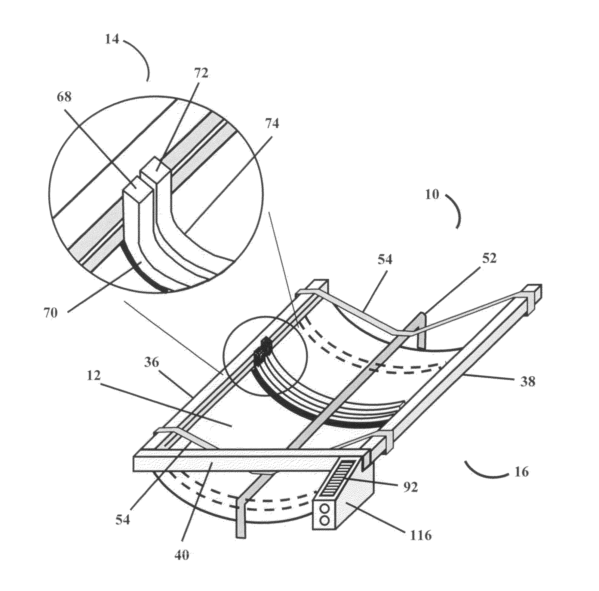
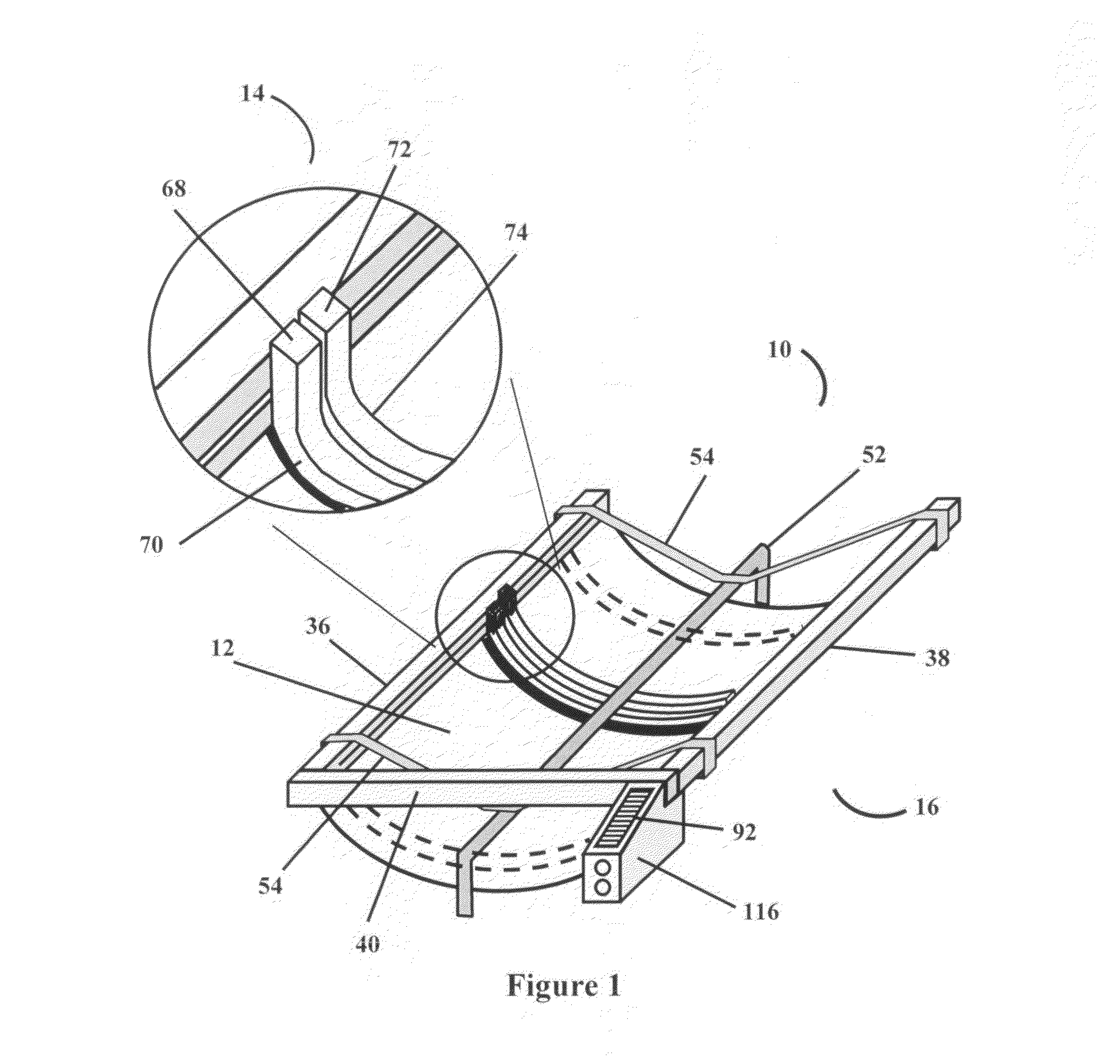
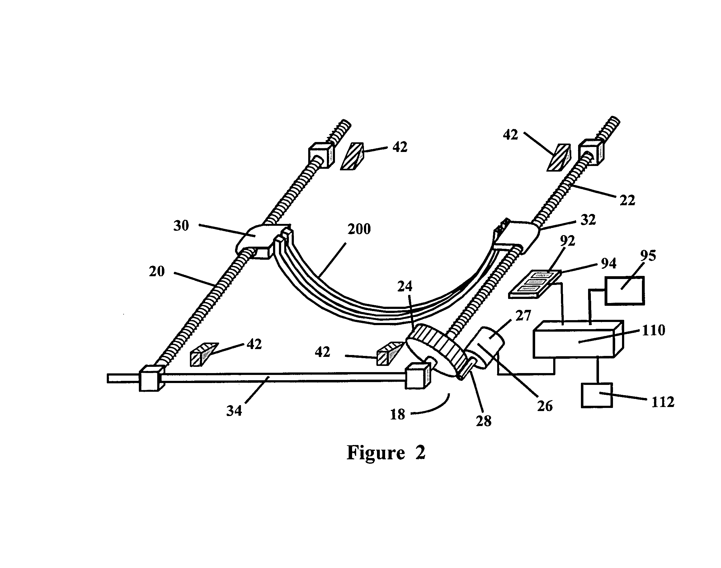
[0075]Referring now to FIG. 1, an autonomous cleaning device and system for a trough reflector panel is shown generally at 10. In the example illustrated, the device 10 is mounted over a curved trough reflector 12. The device 10 and the curved trough reflector 12 may be located on a pedestal or frame such as in a trough reflector park or may be located on the side or rooftop of a residential or commercial building or on the ground. A person skilled in the art will recognize that although a single trough reflector is referred to throughout, it is to be understood that a plurality of devices 10 may also be used with a plurality of curved trough reflectors 12. The device 10 can be used for solar thermal applications such as passive water and air heaters, steam turbines, air conditioning, desalination plants, and the like, and also...


PUM


Abstract

Described herein is a cleaning device for a flat solar panel or a trough reflector panel. The device comprises a cleaning member with a sweeper portion and a scraper portion. The cleaning member is mounted for unidirectional and bidirectional movement over the flat panel or the reflector panel. A rocker bar is connected to the sweeper portion and the scraper portion to rockingly move either the sweeper portion or the scraper portion into contact with the flat panel or the reflector panel as the cleaning member moves over the flat panel or the reflector panel.

Description

TECHNICAL FIELD[0001]The present relates to autonomous cleaning devices, and more particularly to an autonomous ramp device for cleaning a trough reflector panel and a flat solar panel.BACKGROUND[0002]Solar panels are now commonplace as efficient, clean energy sources. Flat panels typically contain a protective transparent cover over a photovoltaic array which converts solar energy to usable electrical power. Curved reflector panels, also commonly referred to as a solar reflector panel or as a trough solar panel reflects incoming solar energy to a concentrated area where a collector is located. The collector may be a thermal type which heats a liquid or air, a photovoltaic surface which generates electricity, or a combination of both. During use, the transparent cover or reflector surface may become dirty as a result of an accumulation of: dust, soil, tree debris, sand, moss, dirt, sap, bugs, bird droppings, water spots and build up or mold, and the like, thereby significantly reduc...

Claims


Application Information

Patent Timeline
Patent Type & Authority Applications(United States)
IPC IPC(8): B08B7/04A46B13/00F24S10/50F24S23/74
CPCY02E10/40Y02B10/20F24S23/74F24S10/50F24S50/00F24S40/20B08B1/30
Inventor ADLER, JEFFREY SCOTTBAIRD, HAROLD RUSSELL
Owner ADLER JEFFREY SCOTT
Learn More