Permanent magnet type motor and method for manufacturing permanent magnet type motor

a permanent magnet type, permanent magnet technology, applied in the direction of dynamo-electric machines, magnetic circuit rotating parts, magnetic circuit shape/form/construction, etc., can solve the problems of poor fluidity on the inner surface of the magnet insertion hole, difficult to apply high-viscosity adhesive, uneven application of high-viscosity adhesive, etc., to prevent low-viscosity adhesive, reduce manufacturing cost, and high quality

Active Publication Date: 2014-02-13
SANYO DENKI CO LTD
View PDF15 Cites 17 Cited by
  • Summary
  • Abstract
  • Description
  • Claims
  • Application Information

AI Technical Summary

Benefits of technology

[0020]According to the invention, the rotor core stack is formed by disposing the core sheet not having the magnet insertion hole in one end of the stacking direction. Since one end of the magnet insertion hole is blocked by the core sheet not having the magnet insertion hole, the magnet insertion hole has a container shape, and thus the low-viscosity adhesive does not leak. After a fixed quantity of low-viscosity adhesive is injected into the magnet insertion hole, the permanent magnet is

Problems solved by technology

However, it is difficult to apply a high-viscosity adhesive with poor fluidity onto an inner surface of the magnet insertion hole.
Particularly, since a small motor has a small magnet insertion hole, it was difficult to evenly apply the high-viscosity adhesive onto the inner surface of the magnet insertion hole, and the irregularity of manufacturing of the rotor increased.
Furthermore, after the permanent magnet is inserted into the magnet insertion hole, si

Method used


Image

  • Permanent magnet type motor and method for manufacturing permanent magnet type motor
  • Permanent magnet type motor and method for manufacturing permanent magnet type motor
  • Permanent magnet type motor and method for manufacturing permanent magnet type motor

Examples


first embodiment

[Configuration of Permanent Magnet Type Motor]

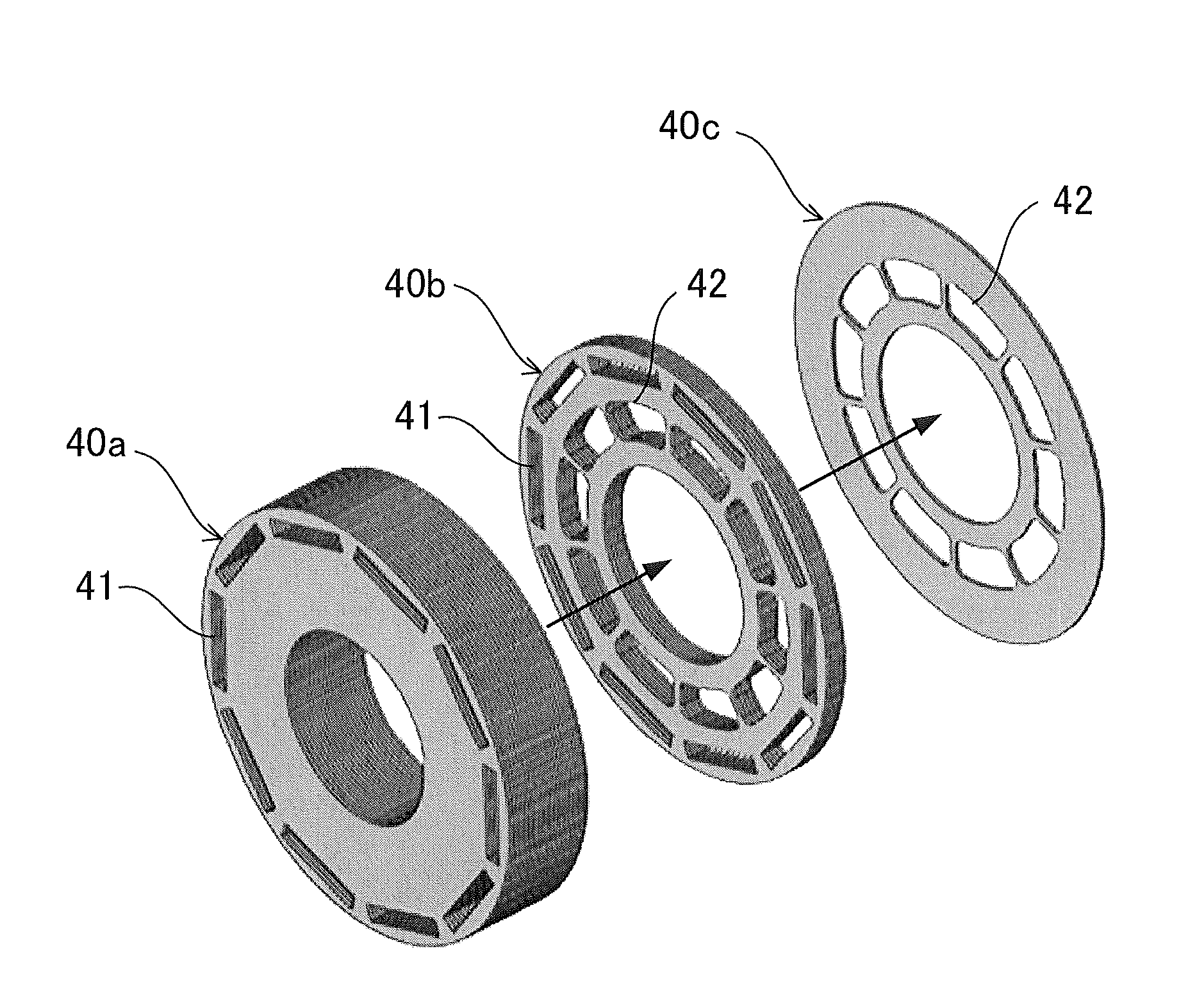
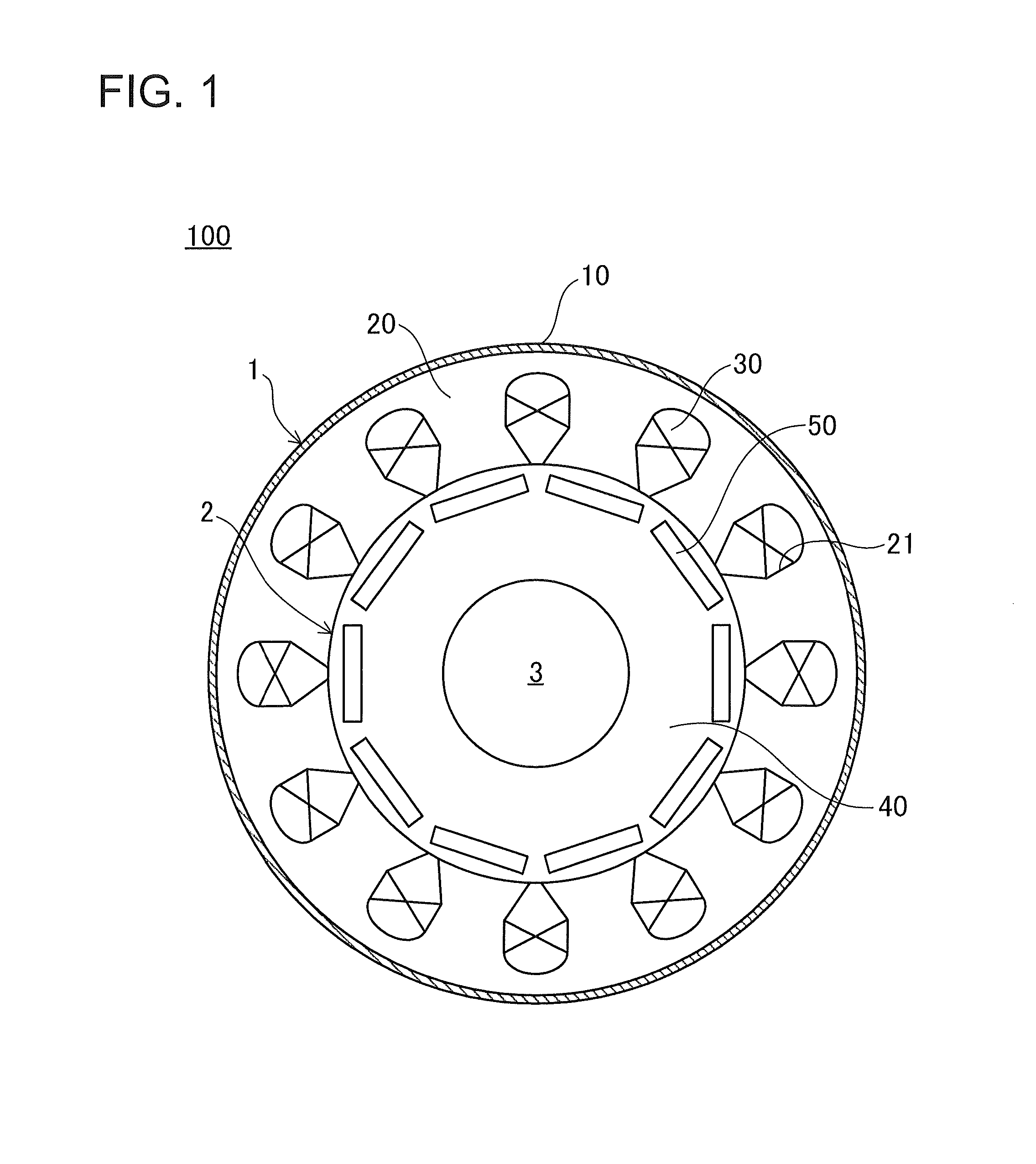
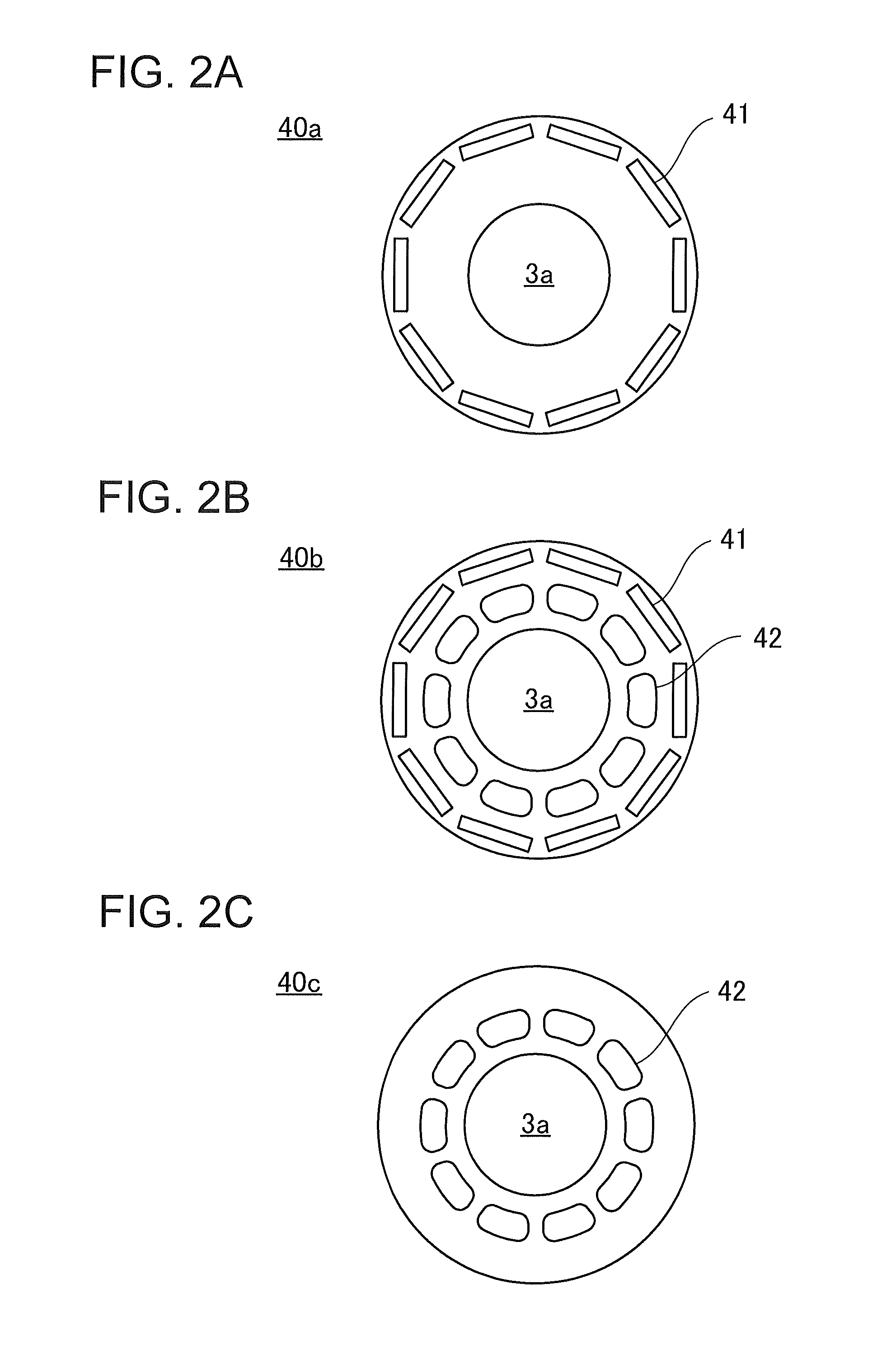
[0036]First, a configuration of a permanent magnet type motor of the first embodiment will be described with reference to FIGS. 1 to 6B. FIG. 1 is a schematic view of an overall configuration of the permanent magnet type motor. FIGS. 2A to 2C are plan views of a core sheet that forms a rotor core stack. FIG. 3 is an exploded perspective view of the rotor core stack. FIGS. 4A and 4B are perspective views of a magnet insertion hole side and a balancing hole side of the rotor core stack. FIGS. 5A and 5B are schematic views of an insertion situation of the permanent magnet after an adhesive is injected. FIGS. 6A and 6B are perspective views of positioning and fitting situation of a shaft and the rotor core stack.

[0037]As an example of the permanent magnet type motor of the embodiment, for example, an IPM motor (Interior Permanent Magnet Motor) is adopted. A permanent magnet type motor 100 illustrated in FIG. 1 is an IPM motor with 10 poles a...

second embodiment

[0084]Next, a permanent magnet type motor 200 and a method for manufacturing the permanent magnet type motor 200 according to a second embodiment will be described with reference to FIGS. 7 to 9C. FIGS. 8A to 8D are perspective views of a seal case structure of a rotor core stack, and side views of a seal case male portion and a seal case female portion of the second embodiment. FIGS. 9A to 9C are an exploded perspective view of a positioning structure of the rotor core stack, and perspective views of a rotor of the second embodiment. In addition, the same components as the permanent magnet type motor 100 according to the first embodiment are denoted by the same reference numerals, and the description thereof will not be repeated.

[0085]As illustrated in FIGS. 8A to 8D, the second embodiment is different from the first embodiment in that the pair of rotor core stacks 40 and 40 is positioned by a seal case structure.

[0086]In the permanent magnet type motor 200 according to the second ...

third embodiment

[0093]Next, a permanent magnet type motor 300 and a method for manufacturing the permanent magnet type motor 300 according to a third embodiment will be described with reference to FIGS. 7 and 10A to 10 C. FIGS. 10A to 10C are an exploded perspective view of a positioning structure of a rotor core stack, and perspective views of a rotor of the third embodiment. In addition, the same components as the permanent magnet type motor 100 according to the first embodiment are denoted by the same reference numerals, and the description thereof will not be repeated.

[0094]As illustrated in FIGS. 10A to 10C, the third embodiment is different from the first embodiment in that the pair of rotor core stacks 40 and 40 is positioned by a thin ring-shaped coupling 320.

[0095]The permanent magnet type motor 300 according to the third embodiment has a plurality of insertion holes 310 formed on the respective facing surfaces of the pair of rotor core stacks 40 and 40. The plurality of insertion holes 31...


PUM


Abstract

A permanent magnet type motor of high quality is achieved which is capable of lowering the manufacturing irregularity of the rotor.
Provided is a method for manufacturing a permanent magnet type motor in which a permanent magnet is incorporated into a rotor cores stack, the method including a process of forming the rotor core stack, by combining a plurality of core sheets having a magnet insertion hole with a core sheet not having the magnet insertion hole, and disposing the core sheet not having the magnet insertion hole in one end of a stacking direction; a process of injecting a low-viscosity adhesive into the magnet insertion hole in which one end is blocked by the core sheets; and a process of bonding and fixing the permanent magnet by inserting the permanent magnet into the magnet insertion hole into which the low-viscosity adhesive is injected.

Description

BACKGROUND[0001]1. Technical Field[0002]The present invention relates to a permanent magnet type motor in which a permanent magnet is incorporated into a rotor core, and a method for manufacturing the permanent magnet type motor.[0003]2. Description of the Related Arts[0004]Motors using a permanent magnet are broadly classified into a surface permanent magnet type (SPM motor) in which the permanent magnet is disposed on a surface of a shaft, and an interior permanent magnet type motor (IPM motor) in which the permanent magnet is incorporated into a rotor core.[0005]Rotor shapes of the IPM motor are very diverse, and a method for manufacturing the rotor is adopted depending on the respective shapes and intended purposes of the motor. Generally, a manufacturing method has been adopted in which after the rotor core is shrinkage fitted to the shaft, an adhesive is applied to both sides of a magnet insertion hole and the permanent magnet, and the permanent magnet is inserted into the mag...

Claims


Application Information

Patent Timeline
IPC IPC(8): H02K1/27
CPCH02K1/276H02K15/03H02K15/12H02K1/27
Inventor MIYASHITA, TOSHIHITOHORIUCHI, MANABU
Owner SANYO DENKI CO LTD
Why Eureka
Try Eureka