
Apparatus and Method for Dimming Signal Generation for a Distributed Solid State Lighting System

a lighting system and dimming signal technology, applied in the direction of electric variable regulation, process and machine control, instruments, etc., can solve the problems of difficult design and implementation, complex control methods, and high cost of prior art led bulbs and systems, and achieve the effect of reducing cost, reducing manufacturing costs, and saving consumers

Inactive Publication Date:
View PDF9 Cites 27 Cited by
  • Summary
  • Abstract
  • Description
  • Claims
  • Application Information

AI Technical Summary

Benefits of technology

The present invention provides a lower cost solution for LED-based lighting by replacing traditional triac dimmer switches and other legacy wall-mounted switches. It also provides compatibility with existing standards such as Edison-based sockets and allows for dimmable LED-based lighting, including remote control and color control. The invention has a simple design and is easy to install and replace. Additionally, the invention includes a dimming signal generator apparatus with improved regulation at low LED currents and a transfer characteristic format to increase stability and reduce flickering during dimming.

Problems solved by technology

Prior art LED bulbs and systems, however, tend to be overly complicated and typically incompatible with existing dimmer switches.
Some require control methods that are complex, some are difficult to design and implement, and others require many electronic components.
A large number of components results in an increased cost and reduced reliability.
Other attempts provide solutions outside the original power converter stages, adding additional feedback and other circuits, rendering the LED driver even larger and more complicated.
A typical dummy load and special circuitry is required to support stable operation of a dimmer switch by providing a load to the dimmer during turn on, typically at a frequency of 60 Hz or 120 Hz, and reduces energy conversion efficiency.
The significant gap between the high voltages of an input AC voltage and the lower DC voltages required for LEDs needs complex power conversion circuitry which may have as many as forty to seventy components, for example, with additional 10%-15% power losses from the conversion.
In addition, a typical triac dimmer presents a comparatively poor interface to an AC line for solid state lighting, corrupting the power factor, introducing additional, nonfundamental harmonics, creating electromagnetic interference (“EMI”) and audio noise problems, and increasing the input RMS current, further requiring corresponding increases in the value of service circuit breakers.

Method used


Image

  • Apparatus and Method for Dimming Signal Generation for a Distributed Solid State Lighting System
  • Apparatus and Method for Dimming Signal Generation for a Distributed Solid State Lighting System
  • Apparatus and Method for Dimming Signal Generation for a Distributed Solid State Lighting System

Examples


Embodiment Construction

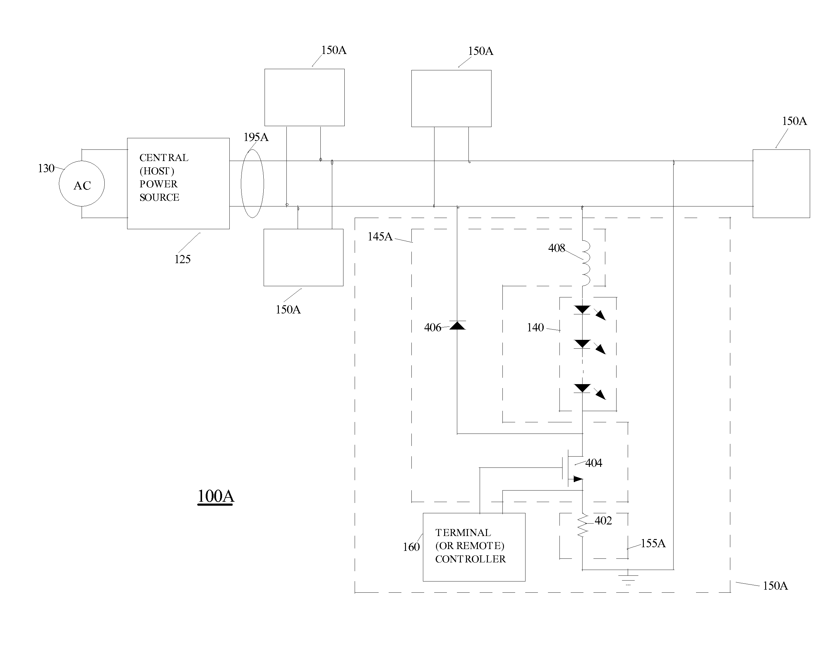
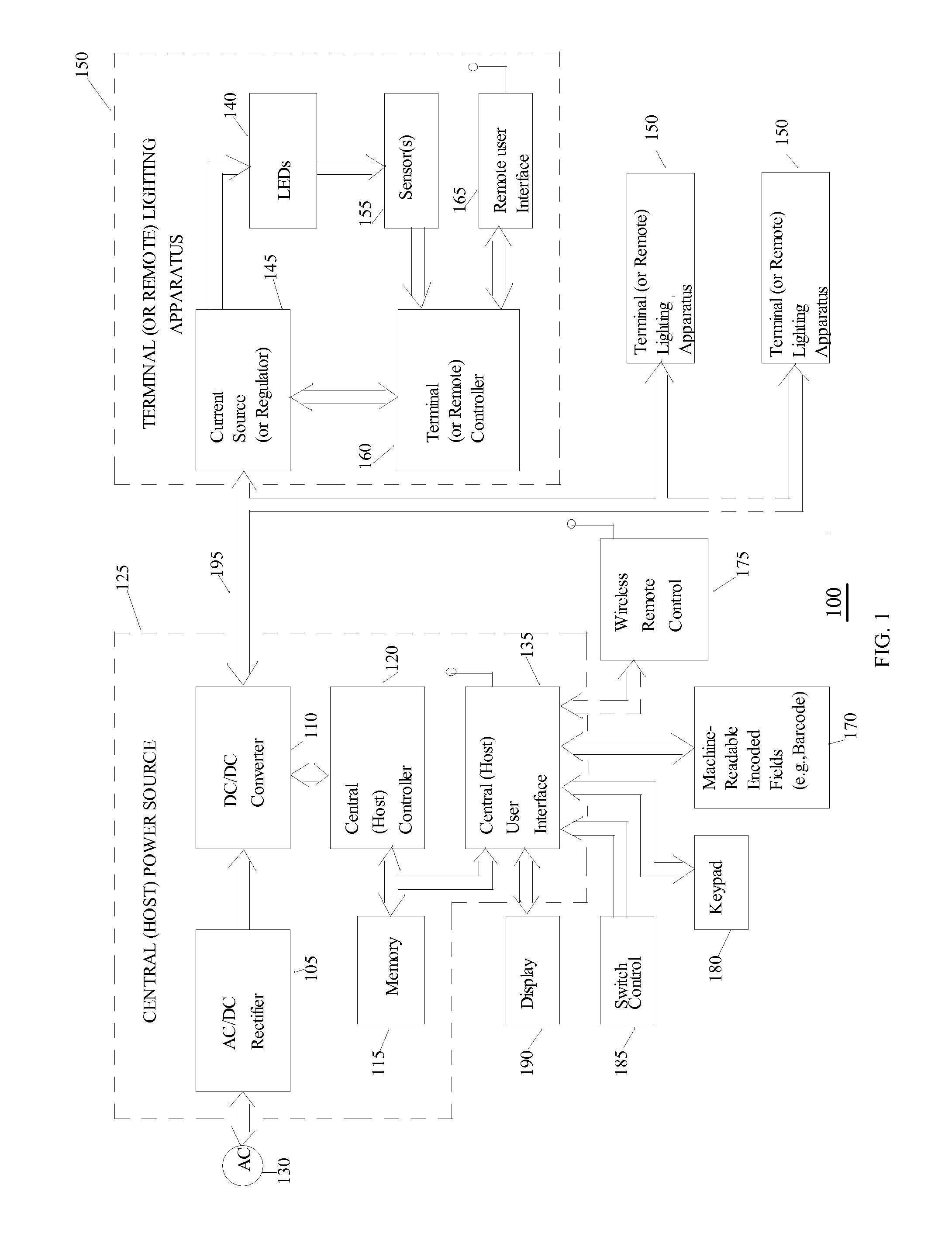
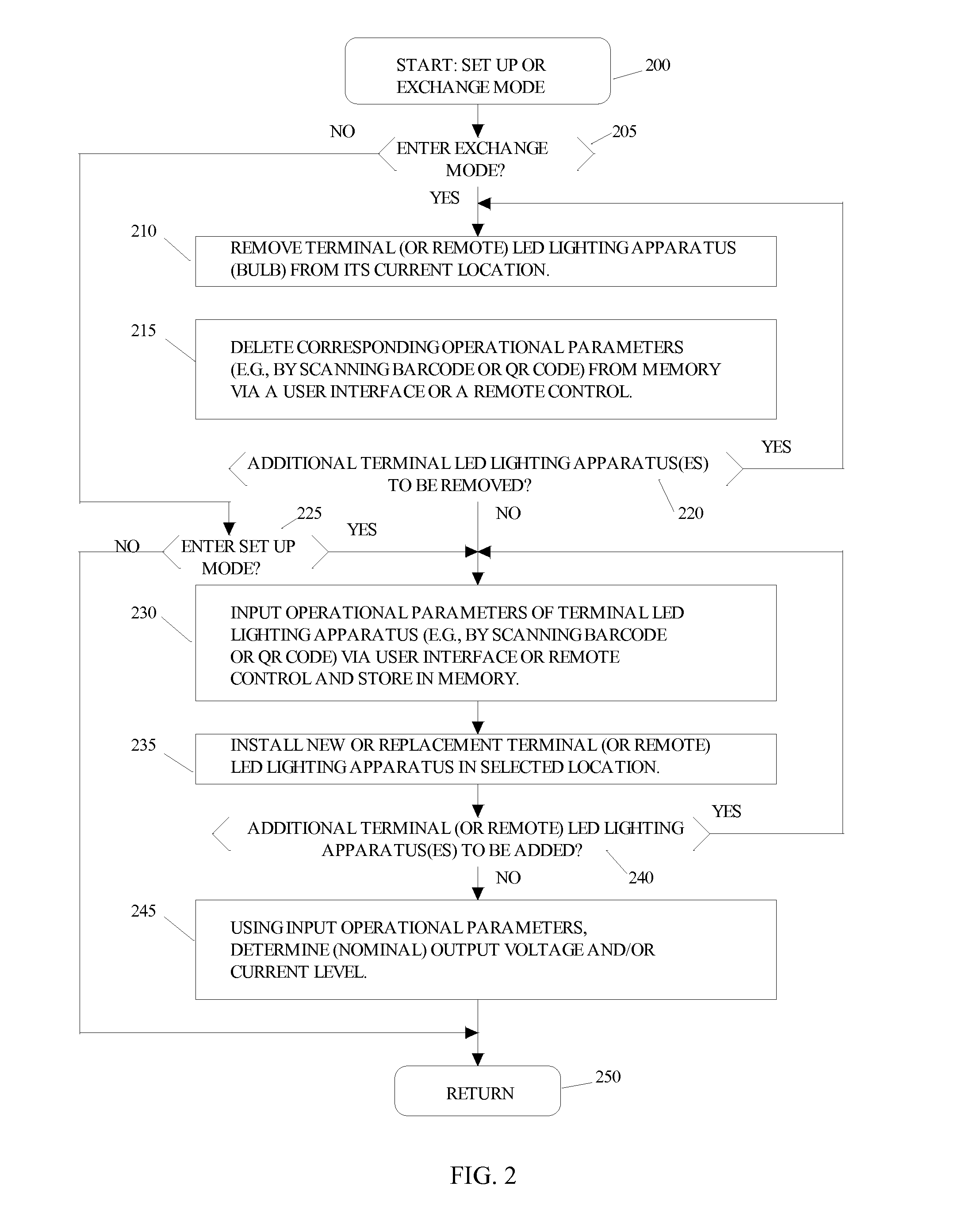
[0075]While the present invention is susceptible of embodiment in many different forms, there are shown in the drawings and will be described herein in detail specific exemplary embodiments thereof, with the understanding that the present disclosure is to be considered as an exemplification of the principles of the invention and is not intended to limit the invention to the specific embodiments illustrated. In this respect, before explaining at least one embodiment consistent with the present invention in detail, it is to be understood that the invention is not limited in its application to the details of construction and to the arrangements of components set forth above and below, illustrated in the drawings, or as described in the examples. Methods and apparatuses consistent with the present invention are capable of other embodiments and of being practiced and carried out in various ways. Also, it is to be understood that the phraseology and terminology employed herein, as well as...


PUM


Abstract

Exemplary systems, methods and apparatuses for providing dimming in a distributed solid-state lighting system are disclosed. An exemplary dimming signal generator is coupleable to a controller or a current generator for a plurality of LEDs, and includes a first resistive voltage divider to sense an input DC voltage; a current sensor to sense a current level of the plurality of LEDs; a first operational amplifier to compare the sensed input DC voltage to a reference voltage level and to provide a comparator output signal; and a current path to combine the comparator output signal with the sensed LED current level to provide a combined signal for current level feedback for control of the LED current level. The dimming signal generator may optionally include other components to generate a PWM signal and also to provide a resistive network to divert LED current in response to the comparator output signal.

Description

CROSS-REFERENCE TO RELATED APPLICATIONS[0001]This application is continuation-in-part of and claims priority to U.S. patent application Ser. No. 13 / 664,068, filed Oct. 30, 2012, inventors Vladimir Korobov et al., entitled “Dimmable Solid State Lighting System, Apparatus and Method, with Distributed Control and Intelligent Remote Control”, which is a conversion of and claims priority to U.S. Provisional Patent Application Ser. No. 61 / 606,837, filed Mar. 5, 2012, inventors Vladimir Korobov et al., entitled “A Power Control Unit for Power Supply to Driverless LED Lighting Apparatuses”, which are commonly assigned herewith, the entire contents of which are incorporated herein by reference with the same full force and effect as if set forth in their entireties herein, and with priority claimed for all commonly disclosed subject matter.FIELD OF THE INVENTION[0002]The present invention in general is related to providing power through a centralized host power source to a plurality of distri...

Claims


Application Information

Patent Timeline
Patent Type & Authority Applications(United States)
IPC IPC(8): H05B33/08H05B44/00
CPCH05B33/0848H05B45/24H05B45/10H05B45/46H05B45/375H05B45/3725H05B45/38H05B45/385H05B45/14
Inventor LIVSCHITZ, LEONARD SIMONSHTEYNBERG, ANATOLYDVADNENKO, VLADIMIR Y.
Learn More