
Internal antenna of mobile terminal

a mobile terminal and antenna technology, applied in the field of antennas of mobile terminals, can solve the problems of increasing the difficulty of providing multiples, affecting the radiation performance of the antennas in the mobile terminal, and unable to add additional internal antennas for multi-media related communications and audio communications for each of the different protocols, so as to achieve the effect of small overall thickness

Active Publication Date: 2014-02-13
SAMSUNG ELECTRONICS CO LTD
View PDF3 Cites 3 Cited by
  • Summary
  • Abstract
  • Description
  • Claims
  • Application Information

AI Technical Summary

Benefits of technology

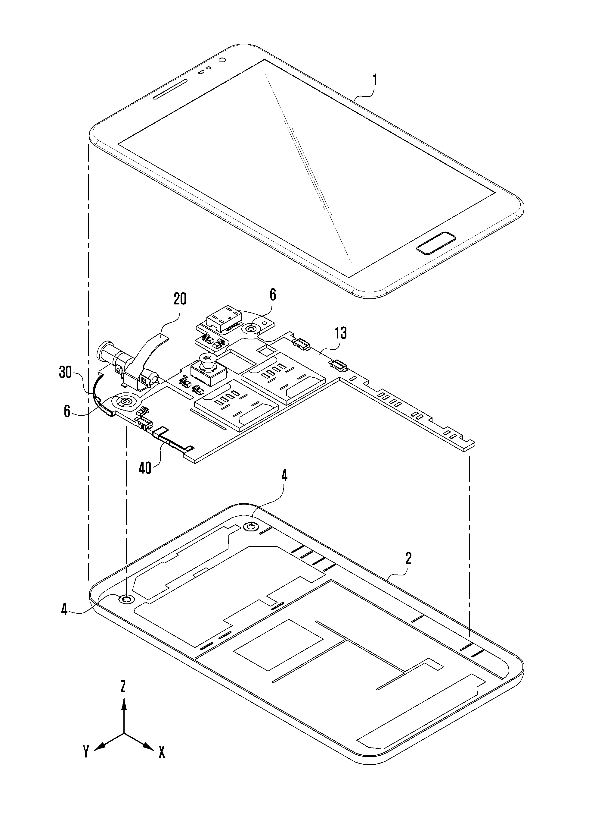
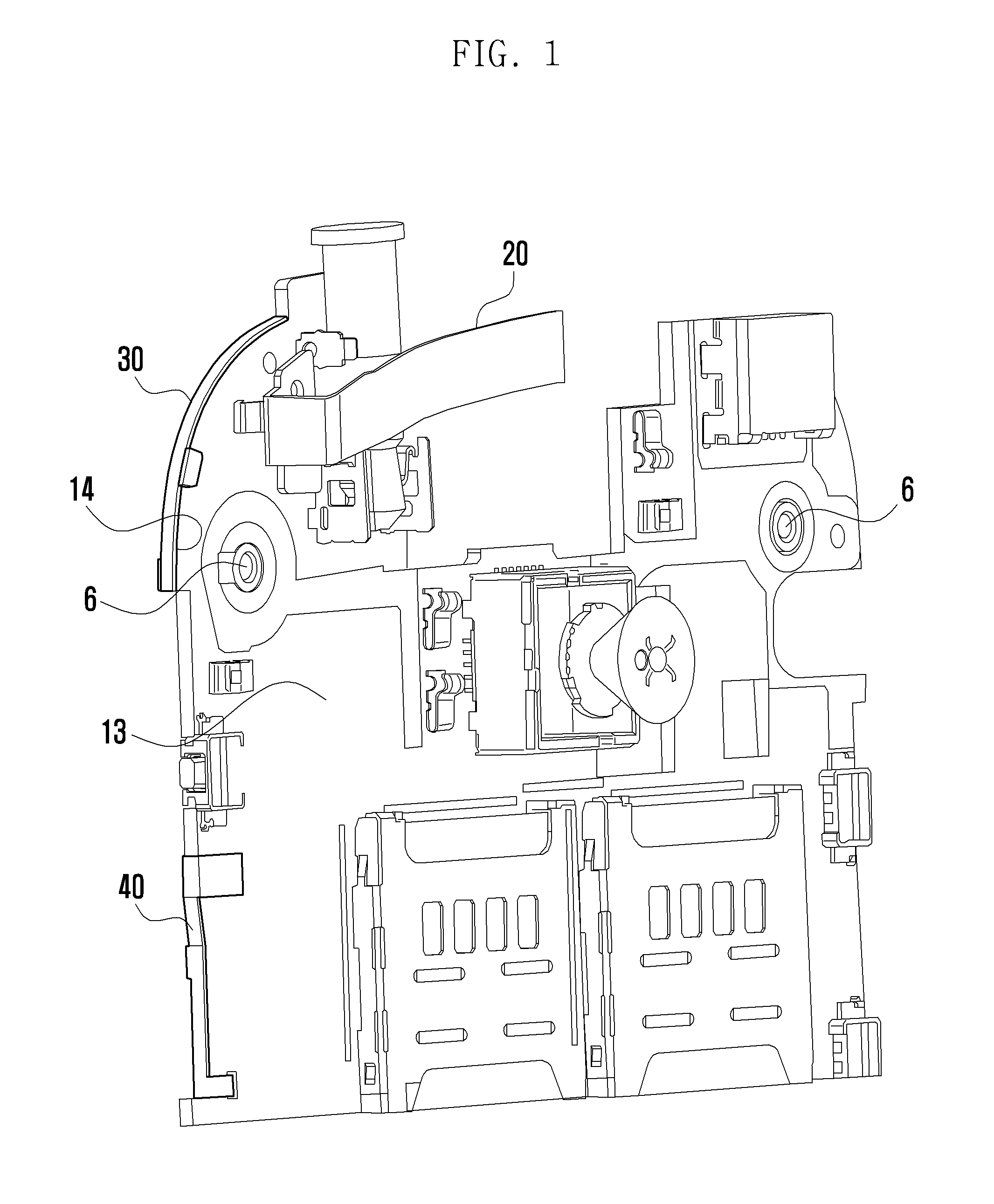
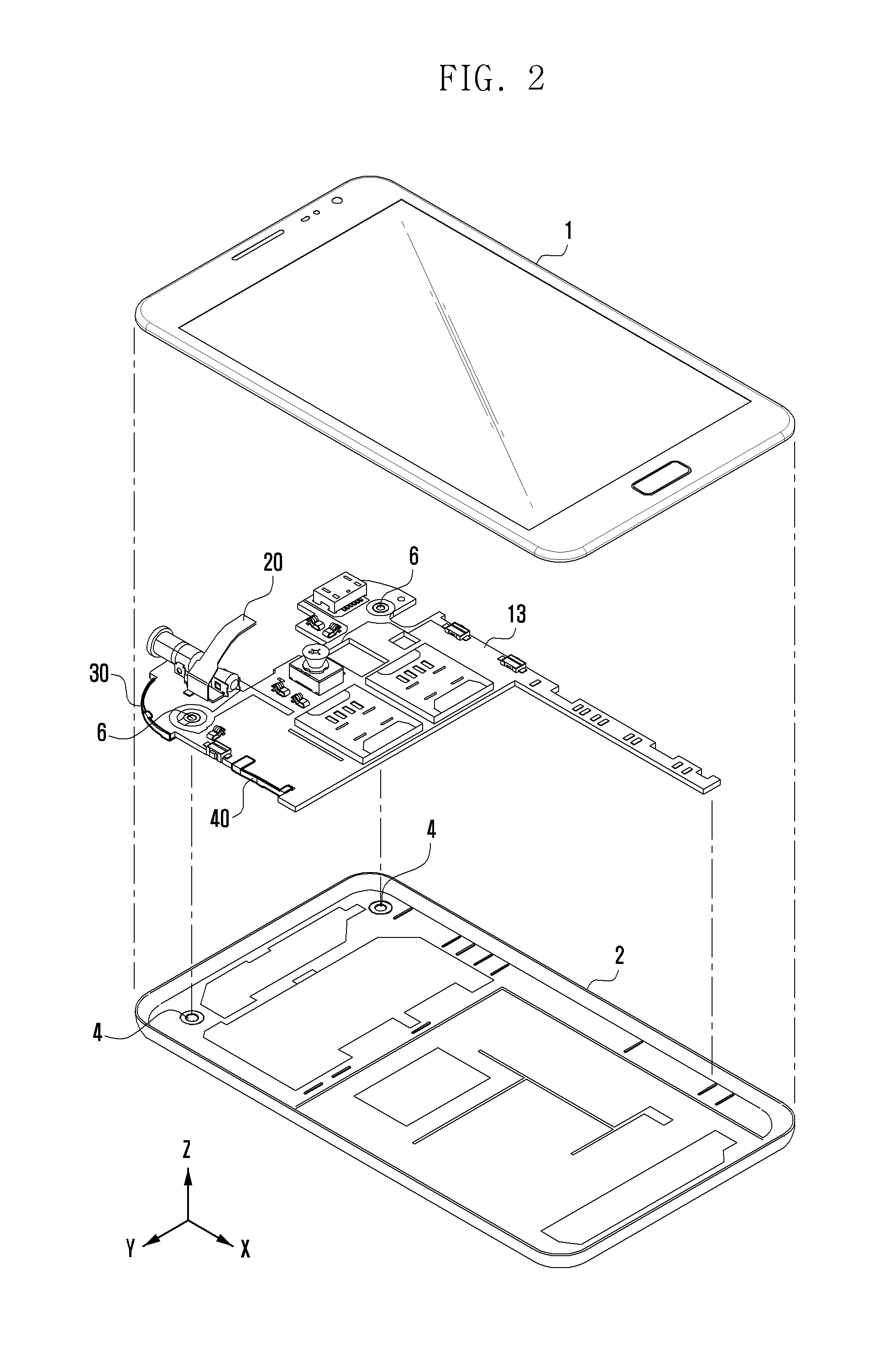
This patent describes an internal antenna for a mobile phone that allows for a thinner phone while still providing space for multiple components. The antenna is stable and doesn't move or separate during use. Additionally, the design improves the antenna's performance by reducing interference from the user's hand when making calls or sending texts.

Problems solved by technology

In addition, as multimedia-related data communication increases, there is increasing difficultly to provide a multiple service with one audio dedicated communication antenna, and thus an exclusive antenna for data communication becomes necessary.
Thus, as there is already difficulty in securing space for mounting two or more internal antennas in limited space, to add additional separate internal antennas for multi-media related communications and audio communications for each of the different protocols is not possible, or comes at a tradeoff of a larger-size portable terminal or the elimination of some of the functional modules that consumers have come to expect in such mobile terminals.
Thus, a radiation performance of the antennas in the mobile terminal is greatly deteriorated, as compared with transmissions in a conventional external antenna.
However, because an internal structure of the mobile terminal is technically arranged in a small area, it is quite difficult to freely change or rearrange the internal structure in contemplation of a user's grip of the mobile terminal.
Therefore, there is difficulty in embodying a structure with an antenna pattern arranged to avoid interference by a user's hand.

Method used


Image

  • Internal antenna of mobile terminal
  • Internal antenna of mobile terminal
  • Internal antenna of mobile terminal

Examples


Embodiment Construction

[0021]Hereinafter, exemplary embodiments of the present invention are described in detail with reference to the accompanying drawings. The same reference numbers are used throughout the drawings to refer to the same or like parts. The views in the drawings are schematic views provided only for illustrative purposes, and are not intended to be to scale or correctly proportioned. Detailed descriptions of well-known functions and structures incorporated herein may be omitted to avoid obscuring appreciation of the subject matter of the present invention by a person of ordinary skill in the art that can be caused by lengthy descriptions of well-known functions and structures.

[0022]Hereinafter, prior to disclosing a detailed exemplary description of the present invention, a person of ordinary skill in the art should understand and appreciate that for convenience of description, the examples discussed herein regarding a mobile terminal according to an exemplary embodiment of the present in...


PUM


Abstract

An antenna of a mobile includes at least two internal antennas and a printed circuit board disposed between a front cover and a rear cover. The printed circuit board includes at least one first antenna mounted on an upper surface and the printed circuit board having at least one fastening opening therein. A second antenna is mounted in an upper portion of a side surface of the printed circuit board and included a protruded portion of one end protruded from a body and in which the protruded portion is fastened to the fastening opening to be fastened to a side surface of the printed circuit board and the mobile terminal can be produced having a reduced thickness.

Description

CLAIM OF PRIORITY[0001]This application claims the benefit of priority under 35 U.S.C. §119(a) from a Korean patent application filed on Aug. 13, 2012 in the Korean Intellectual Property Office and assigned Serial No. 10-2012-0088376, the entire disclosure of which is hereby incorporated by reference in its entirety.BACKGROUND[0002]1. Field of the Invention[0003]The present disclosure relates to an antenna of a mobile terminal. More particularly, the present invention relates to an internal antenna of a mobile terminal that can support a multi-band and a multi-function operation and that can secure various radiator mounting space.[0004]2. Description of the Related Art[0005]Mobile terminals require antennas for wirelessly transmitting and receiving various types of communication. Nowadays, due to aesthetic design reasons of and performance, an internal antenna is widely used rather than a removable or an extendible external antenna. Entire antennas including an internal antenna / remo...

Claims


Application Information

Patent Timeline
IPC IPC(8): H01Q1/24
CPCH01Q1/243H01Q1/088H01Q1/38H01Q1/24H01Q5/00H01Q21/06H04B1/38
Inventor PARK, JEONGWANJANG, BYUNGCHANKIM, SUKHOKIM, SEUNGHWANBYUN, JOONHO
Owner SAMSUNG ELECTRONICS CO LTD
Learn More