
Silent chain

Active Publication Date: 2014-02-13
TSUBAKIMOTO CHAIN CO
View PDF27 Cites 6 Cited by
  • Summary
  • Abstract
  • Description
  • Claims
  • Application Information

AI Technical Summary

Benefits of technology

The present invention provides a silent chain that reduces weight and widthwise size by reducing the length of the short pin while preventing excessive stress concentration in the short pin of the rocker pin. The silent chain also prevents damage to a stopper provided in the short pin while implementing a reduction in widthwise size. The silent chain includes a plurality of guide rows, a plurality of non-guide rows, and a plurality of rocker pins that couple each of the guide rows and each of the non-guide rows adjacent to each other in a longitudinal direction such that the guide row and the non-guide row are bendable. The short pin is inserted into the guide pin hole of each of the guide plates and the second pin hole of each of the second plates in the non-guide row, and the first and second adjacent plates have first and second contact portions, respectively. The short pin has first and second stoppers that come into contact with the first and second contact portions, respectively, preventing the short pin from being positioned in the second pin hole of the first adjacent plate and the second pin hole of the second adjacent plate.

Problems solved by technology

As a result, there have been a problem that the weight of the silent chain is increased and a problem that the size of the silent chain is increased in the width direction of the chain.

Method used


Image

  • Silent chain
  • Silent chain
  • Silent chain

Examples


embodiments

[0036]Hereinbelow, embodiments of the present invention will be described with reference to FIGS. 1 to 8.

[0037]FIGS. 1 to 3 are views for explaining a first embodiment.

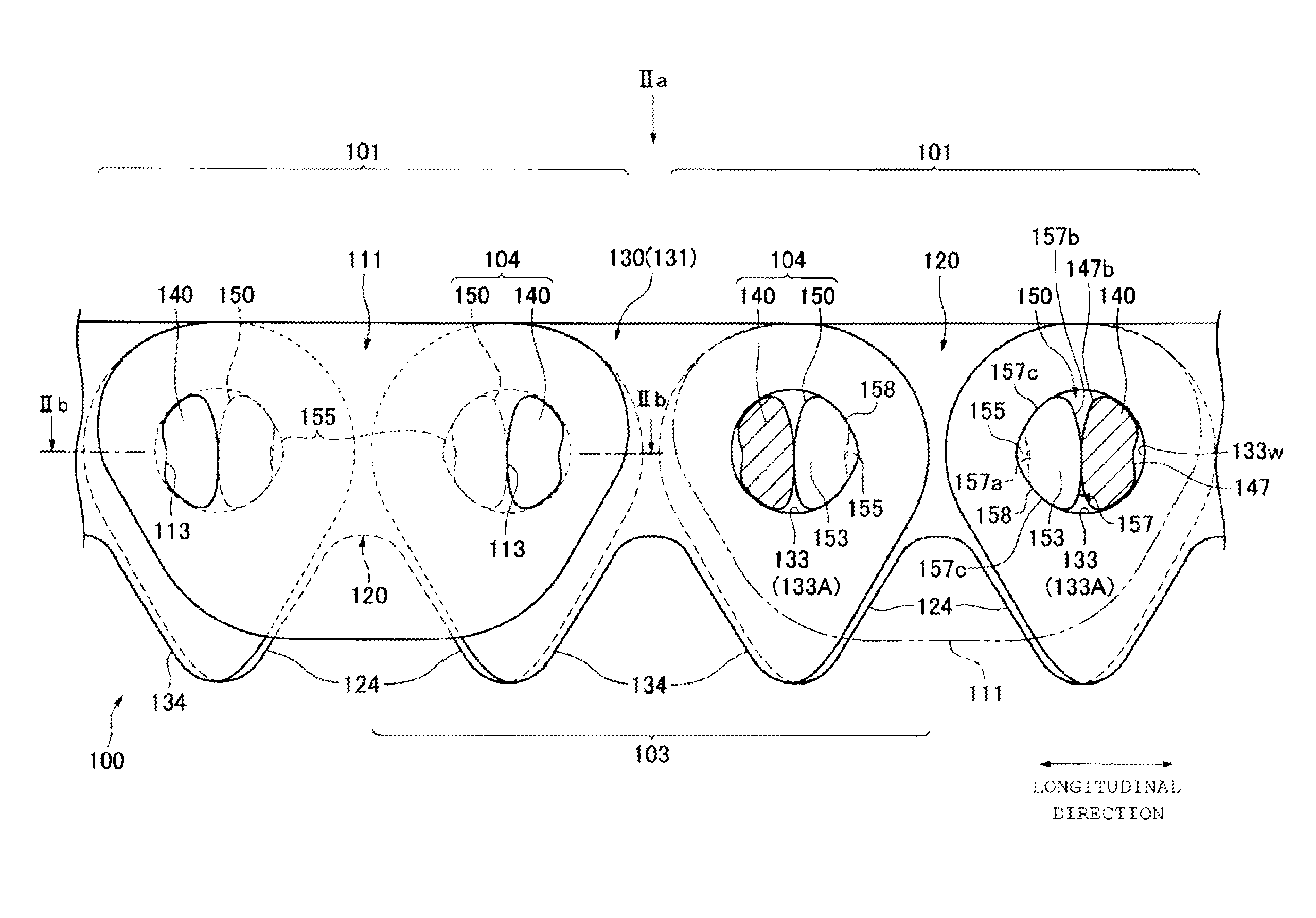
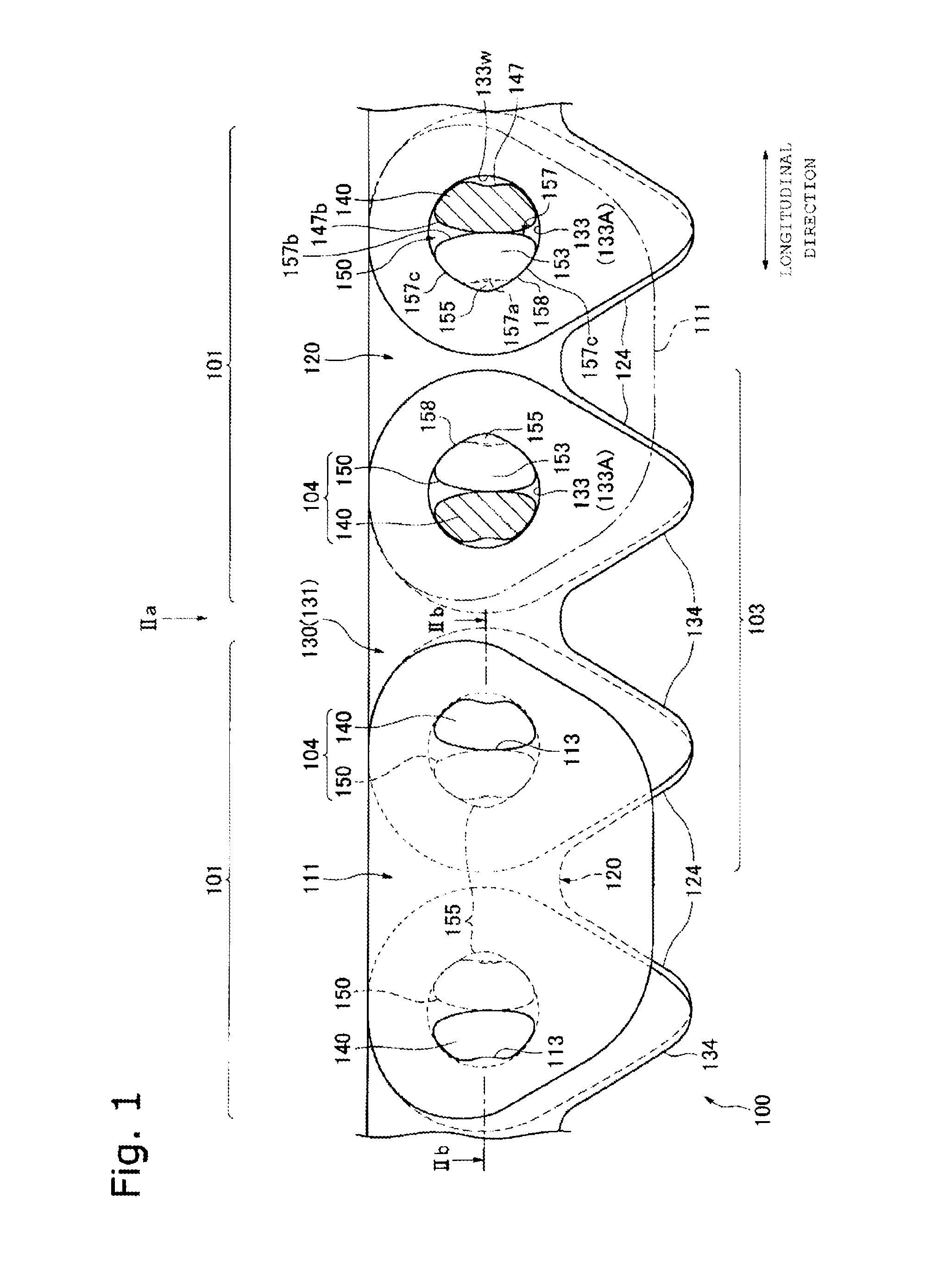
[0038]Referring to FIG. 1, in the first embodiment, a silent chain 100 (hereinafter referred to as a “chain 100”) is an endless chain, and is provided in a chain drive system. The chain drive system is used in power equipment mounted on an automobile.

[0039]In addition to the chain 100, the chain drive system includes a sprocket system including a plurality of sprockets around which the chain 100 is wound. At least one of the plurality of sprockets is a driving sprocket rotationally driven by an engine of the power equipment as a chain driving device.

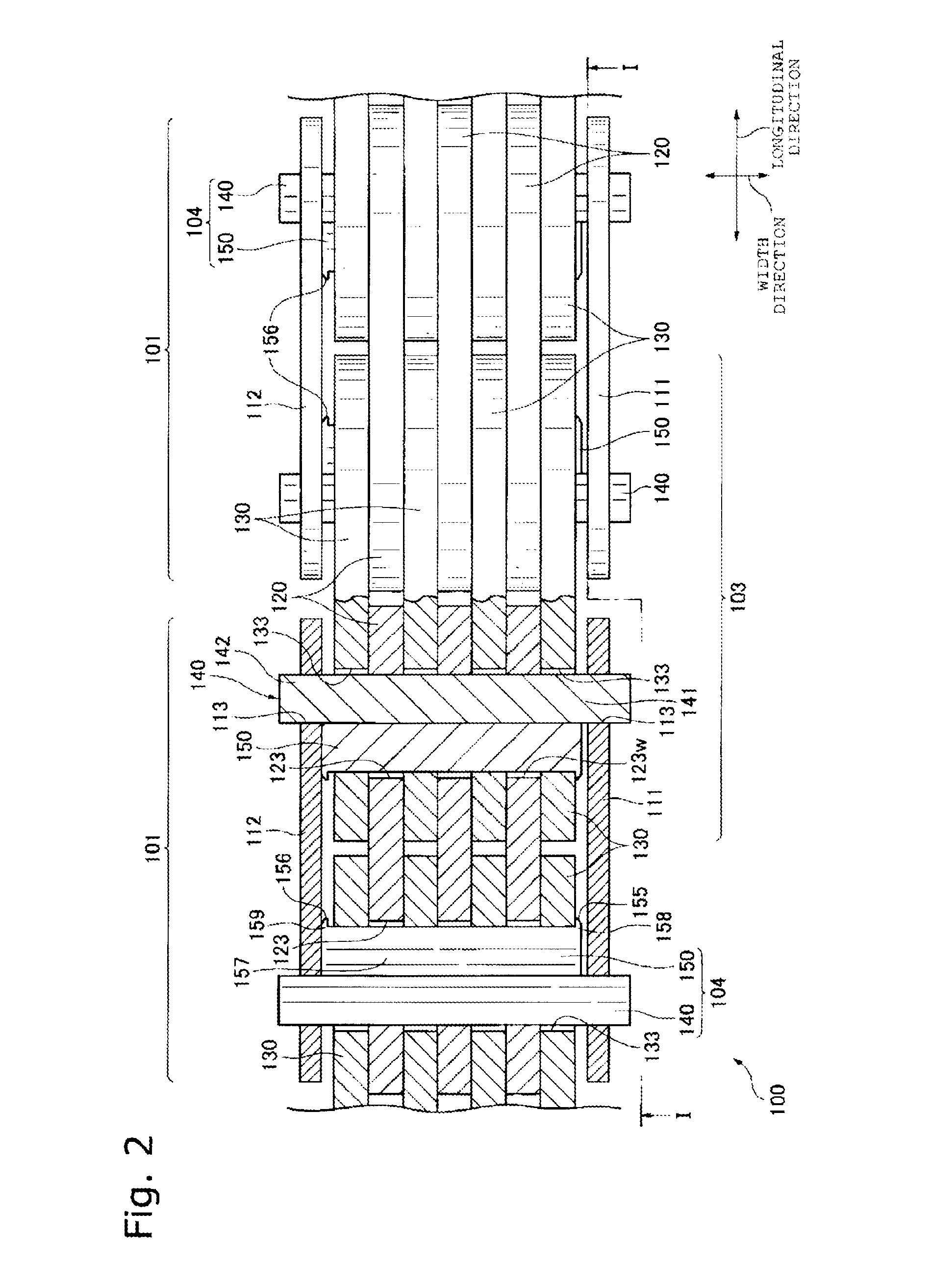
[0040]Referring to FIGS. 1 and 2, the chain 100 includes a plurality of guide rows 101, a plurality of non-guide rows 103, and a plurality of rocker pins 104. The guide row 101 and the non-guide row 103 adjacent to each other in a longitudinal direction are coupled by the ...


PUM


Abstract

There is provided a silent chain that is reduced in weight and widthwise size by reducing the length of a short pin while preventing the occurrence of excessive stress concentration in the short pin of a rocker pin including a long pin and the short pin. The short pin of the rocker pin extends through all plates of the guide row and all plates of the non-guide row in the width direction. The short pin is provided with a first stopper, and a second stopper. A first end surface of the short pin is prevented from being positioned in a first adjacent pin hole by contact between the first stopper and the first contact portion, and a second end surface of the short pin is prevented from being positioned in a second adjacent pin hole by contact between the second stopper and the second contact portion.

Description

BACKGROUND OF THE INVENTION[0001]1. Field of the Invention[0002]The present invention relates to a silent chain in which a guide row and a non-guide row adjacent to each other in a longitudinal direction are coupled so as to be bendable by a rocker pin including a long pin and a short pin.[0003]The silent chain is provided in a chain drive system, and the chain drive system is used in, e.g., power equipment for an automobile.[0004]2. Description of the Related Art[0005]Conventionally, in a silent chain having a rocker pin that couples a guide row and a non-guide row such that the guide row and the non-guide row are bendable, the rocker pin includes a long pin and a short pin.[0006]Referring to FIG. 9, in a silent chain 500, a long pin 540 of a rocker pin 504 is held in guide pin holes 513 of a pair of guide plates 511 and 512 so as not to slip out therefrom, and is inserted into first pin holes 523 of a plurality of first plates 520 and second pin holes 533 of a plurality of second ...

Claims


Application Information

Patent Timeline
IPC IPC(8): F16G13/04
CPCF16G13/04F16G13/08
Inventor SASAKI, TAKEOTOHARA, TAKASHI
Owner TSUBAKIMOTO CHAIN CO
Learn More