Transmission ratio variable device

a technology of transmission ratio and variable device, which is applied in the direction of mechanical equipment, transportation and packaging, etc., can solve the problems of affecting the the preload applied to and the deformation amount of the elastic member may vary, so as to achieve good meshing state of the nutation gear mechanism

Inactive Publication Date: 2014-02-13
JTEKT CORP
View PDF3 Cites 3 Cited by
  • Summary
  • Abstract
  • Description
  • Claims
  • Application Information

AI Technical Summary

Benefits of technology

[0007]The invention provides a transmission ratio variable device configured such that variation in a preload applied to a nutation gear mechanism due to an assembly error and the like is reduced, and a good meshing state of the nutation gear mechanism is maintained.

Problems solved by technology

In the conventional structure stated above, a deformation amount of the elastic member may vary due to an assembly error and the like, in an early stage of manufacturing of the transmission ratio variable device.
As a result, the preload applied to the nutation gear mechanism may vary, and it may be difficult to maintain the good meshing state of the nutation gear mechanism.
Meanwhile, if the preload is too large, for example, meshing friction between the gears may be increased, which may inhibit smooth operations of the nutation gear mechanism.

Method used


Image

  • Transmission ratio variable device
  • Transmission ratio variable device
  • Transmission ratio variable device

Examples


first embodiment

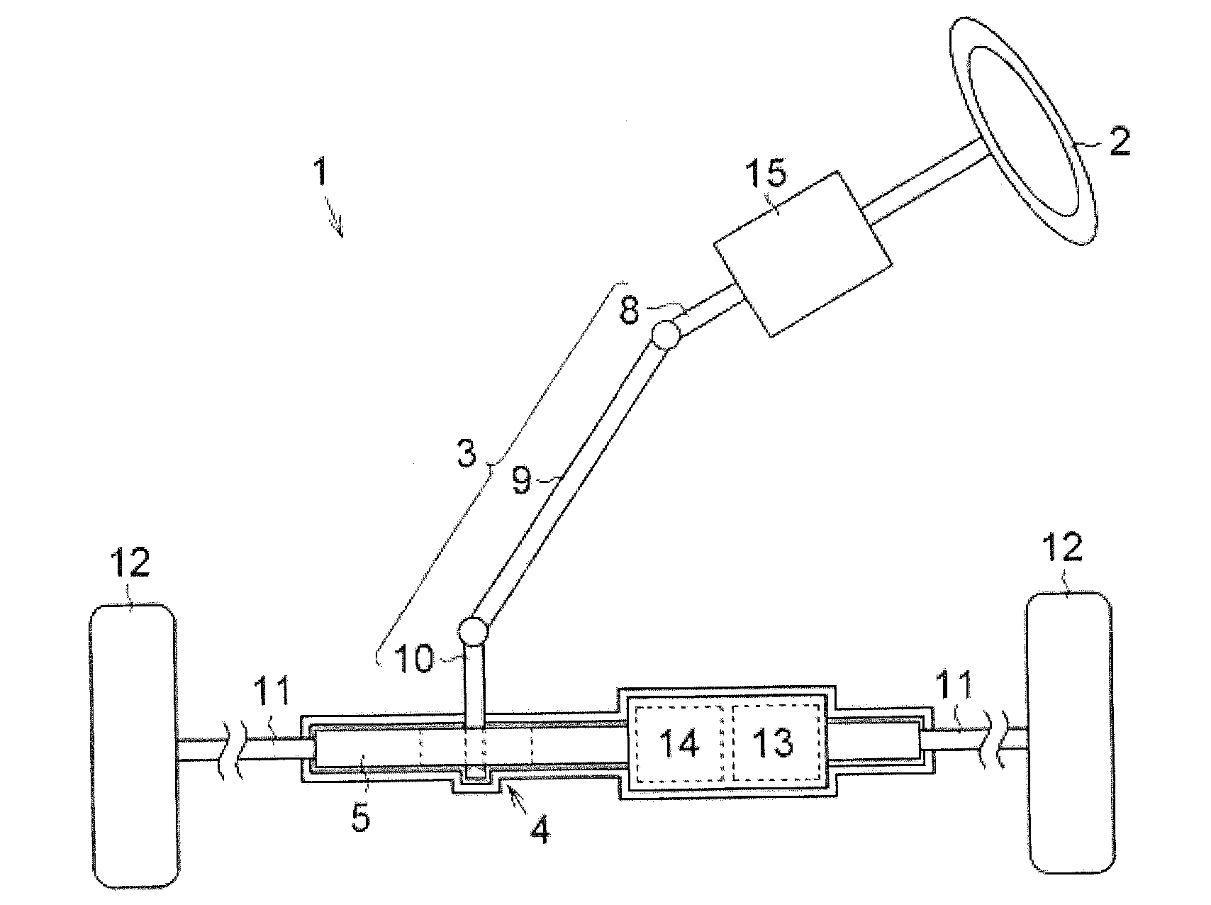
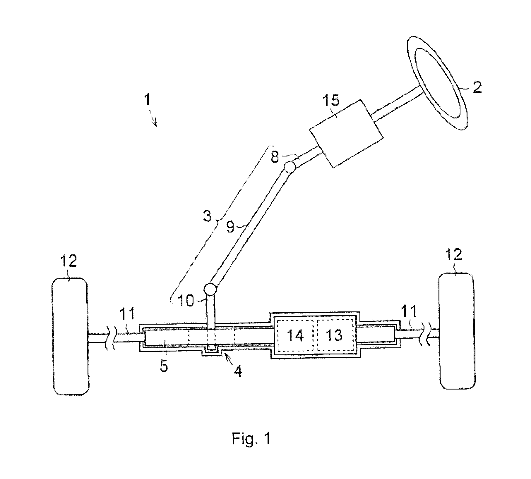
[0022]A first embodiment will be described with reference to the drawings. As shown in FIG. 1, in a vehicle steering system 1, a pinion (not shown) provided in a steering shaft 3 to which a steering wheel 2 is fixed meshes with a rack shaft 5 through a rack-and-pinion mechanism 4. Thus, rotation of the steering shaft 3 in association with a steering operation is converted into a linear reciprocating motion of the rack shaft 5 by the rack-and-pinion mechanism 4. The steering shaft 3 is formed by connecting a column shaft 8, an intermediate shaft 9, and a pinion shaft 10. A linear reciprocating motion of the rack shaft 5 in association with rotation of the steering shaft 3 is transmitted to knuckles (not shown) through tie rods 11 connected to respective ends of the rack shaft 5. Thus, a rudder angle of steered wheels 12, in other words, a traveling direction of a vehicle is changed. The vehicle steering system 1 according to this embodiment is configured as a so-called “rack assist t...

second embodiment

[0072]In the foregoing second embodiment, the soft member 133 is formed of a metallic material such as copper. However, the present invention is not limited to this, and the soft member 133 may be formed of another material such as resin or rubber as long as the soft member 133 has lower mechanical strength than mechanical strength of the preload adjusting plug 101. Alternatively, the soft member 133 may not be provided between the external thread portion 106 and the internal thread portion 95.

[0073]In the foregoing second embodiment, the elongated holes 131a and 131b are formed in the preload adjusting plug 101, and thus, the bridge portions 132a with low mechanical strength are formed on both sides of each elongated hole 131a in the longitudinal direction and the bridge portions 132b with low mechanical strength are formed on both sides of each elongated hole 131b in the longitudinal direction. However, the present invention is not limited to this, low-strength portions with low m...

third embodiment

[0075]In the foregoing third embodiment, knurling is used as the high μ process for increasing the friction coefficient μ performed on the contact surface 143a of the friction plate 143. However, the present invention is not limited to this, and other machining methods such as graining may be used. As the high μ process for increasing the friction coefficient μ, plating may be used to cover the contact surface 143a with a material having a high friction coefficient.

[0076]In the foregoing third embodiment, the high μ process for increasing the friction coefficient μ is performed on the contact surface 143a of the friction plate 143. However, the present invention is not limited to this, and the high μ process for increasing the friction coefficient μ may be performed only on a contact surface 101a (see FIG. 8) of the preload adjusting plug 101, which contacts the friction plate 143, or on both of the contact surfaces 101a and 143a. The high μ process for increasing the friction coeff...


PUM


Abstract

A second shaft is configured by a shaft portion extending outside a housing in which a nutation gear mechanism is housed, a housing portion, and a cylindrical portion. A communicating hole, through which an outside and an inside of the housing portion communicate with each other, is formed in the shaft portion. A preload applying mechanism includes a preload adjusting plug that is screwed to the housing portion and is able to be operated from outside through the communicating hole, a wave washer compressed in accordance with a position of the preload adjusting plug, and a lock nut that is screwed to the housing portion of the second shaft so as to press the preload adjusting plug toward the nutation gear mechanism.

Description

INCORPORATION BY REFERENCE / RELATED APPLICATION[0001]This application claims priority to Japanese Patent Application No. 2012-176001 filed on Aug. 8, 2012 the disclosure of which, including the specification, drawings and abstract, is incorporated herein by reference in its entirety.BACKGROUND OF THE INVENTION[0002]1. Field of the Invention[0003]The invention relates to a transmission ratio variable device.[0004]2. Discussion of Background[0005]Conventionally, there has been a transmission ratio variable device that changes a rotation transmission ratio (a steering gear ratio) between input and output shafts by adding motor-driven rotation to rotation of the input shaft based on a steering operation by using a differential mechanism and transmitting resultant rotation to the output shaft. In US2008 / 0251311 A1, a transmission ratio variable device is described in which a nutation gear mechanism is employed as a differential mechanism. The nutation gear mechanism includes a first gear ...

Claims


Application Information

Patent Timeline
Patent Type & Authority Applications(United States)
IPC IPC(8): F16H3/70
CPCF16H3/70F16H1/321B62D5/008
Inventor SASAKI, HITOSHIMOTOYAMA, SATOSHIYAMAKAWA, TOMONARINATSUME, MASANORI
Owner JTEKT CORP
Why Eureka
Try Eureka