Continuous Reactor and Method for Manufacturing Nanoparticles

a technology of continuous reactor and nanoparticles, which is applied in the direction of nanotechnology, material nanotechnology, transportation and packaging, etc., can solve the problems of not meeting the requirements of mass production and the large limitation of the flow rate of the reaction solution, so as to reduce the risk of solution leakage, prevent the blockage of the channel, and increase the flow rate tolerance

Inactive Publication Date: 2014-02-20
NATIONAL TSING HUA UNIVERSITY
View PDF1 Cites 1 Cited by
  • Summary
  • Abstract
  • Description
  • Claims
  • Application Information

AI Technical Summary

Benefits of technology

[0020]The channel size of diverging and converging channels in the continuous reactor are not particularly limited. For example, it may be in centimeter-scale to enable a higher flow rate tolerance for the continuous reactor, thereby reducing the risk of solution leakage due to overly high pressure to the inner wall of

Problems solved by technology

Also, in 2005, Wagner et al. synthesize silver nanoparticles having a diameter of 5-50 nm using a micro-scaled reactor, but there e

Method used


Image

  • Continuous Reactor and Method for Manufacturing Nanoparticles
  • Continuous Reactor and Method for Manufacturing Nanoparticles
  • Continuous Reactor and Method for Manufacturing Nanoparticles

Examples


example 1

Continuous Reactor for Manufacturing Nanoparticles

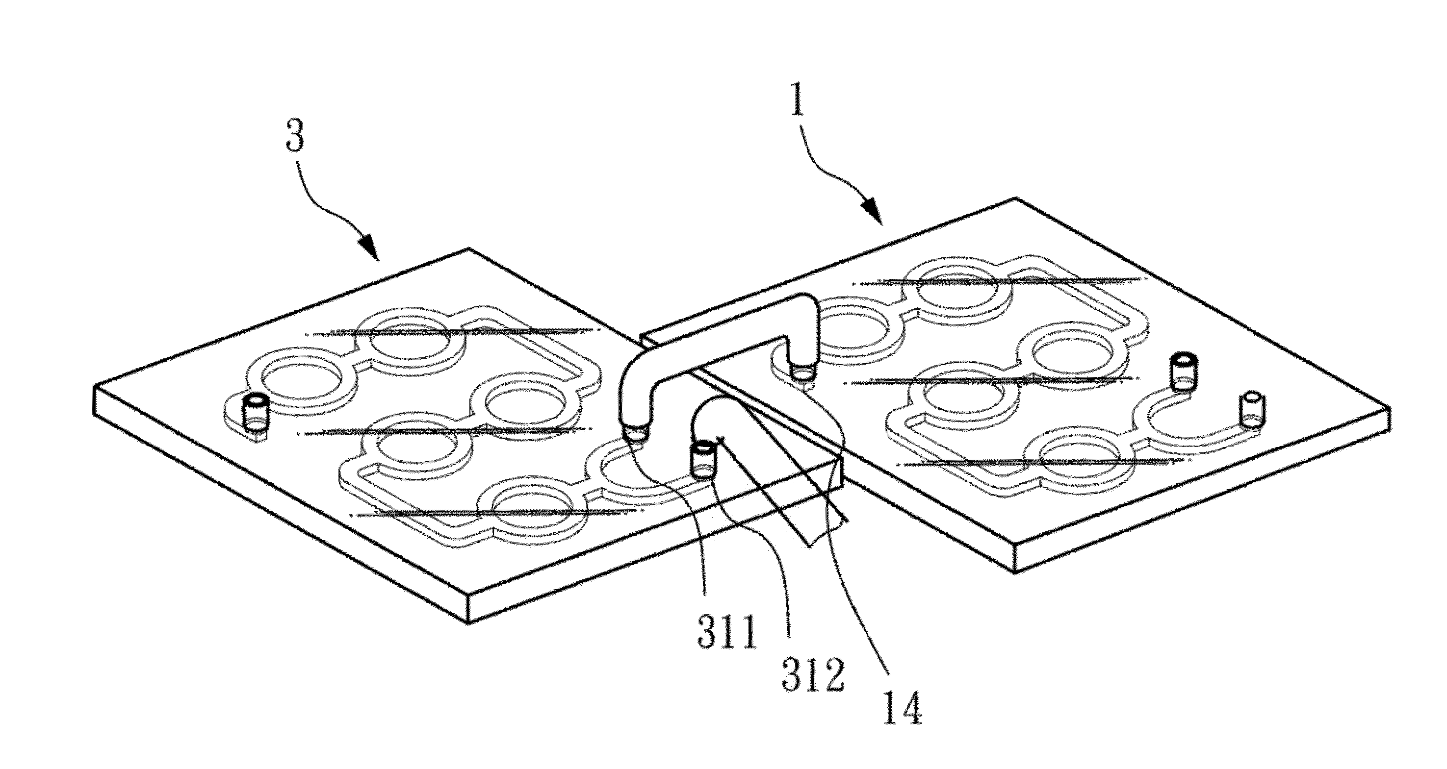
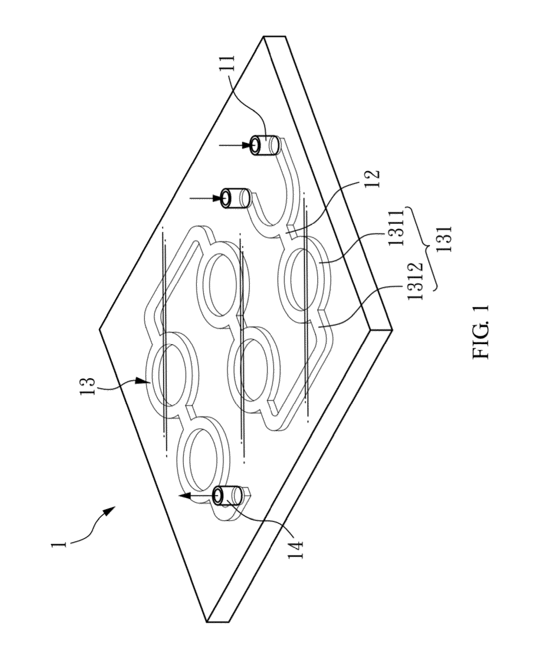
[0037]FIG. 1 shows a first reactor of the continuous reactor for manufacturing nanoparticles of Example 1, which comprises: two first inputs 11; a first mixing part 12 connected to the first inputs 11; a first reaction part 13 comprising five first reaction units 131, each comprising two first diverging channels 1311 and one first converging channel 1312 alternately connected to one another thereby connecting the five first reaction units 131 in series to form a five-times diverging-converging channels. Besides, the first diverging channels 1311 of the first one of the first reaction units 131 are connected to the first mixing part 12. Further, the continuous reactor for manufacturing nanoparticles of Example 1 also comprises a first output 14 connected to the first converging channel 1312 of the fifth one of the first reaction units 131 to output the produced nanoparticles.

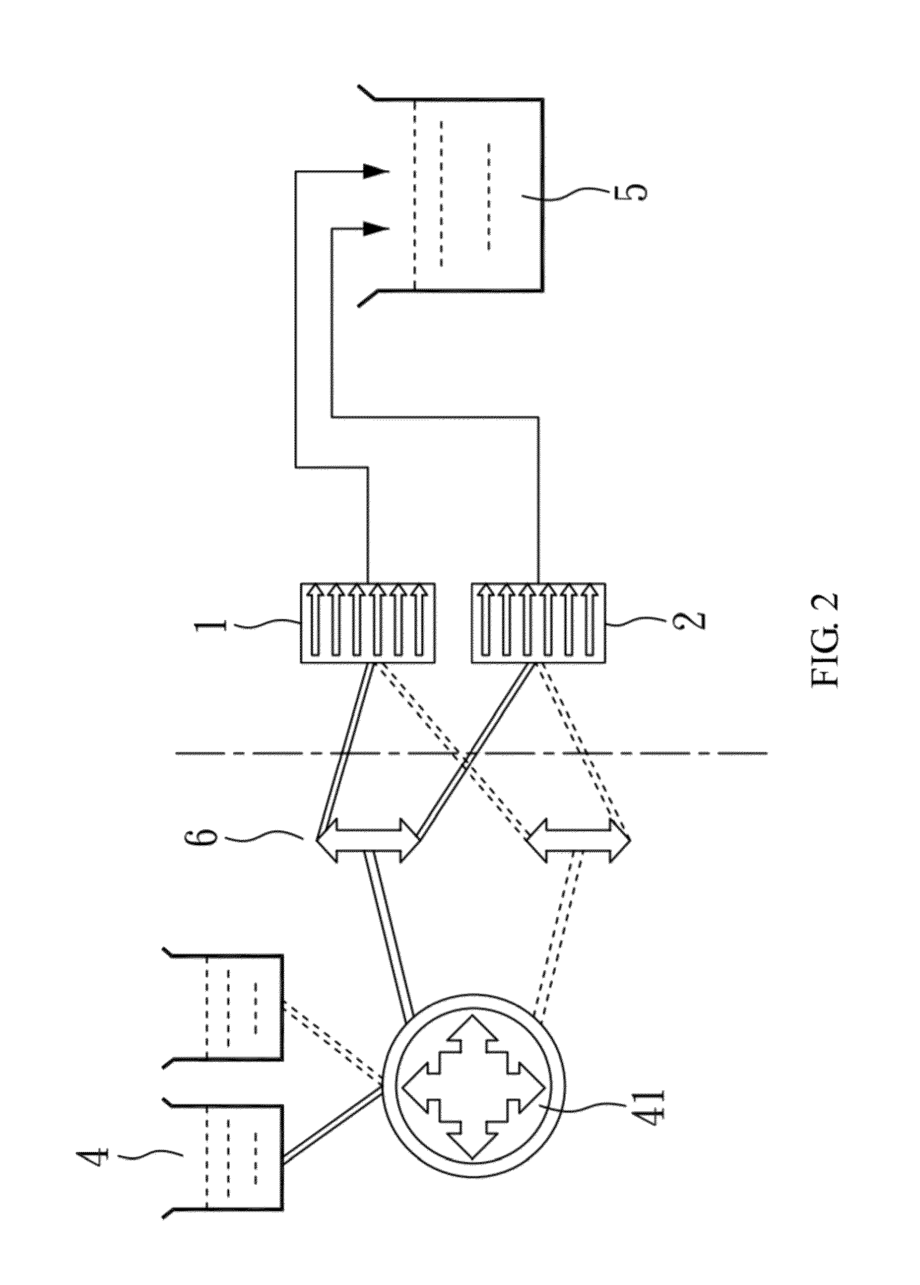
[0038]As illustrated in FIG. 2, in addition to the above fir...

example 2

Preparation of Water-Soluble Silver Nanoparticles

example 2-1

Preparation of Water-Soluble Silver Nanoparticles by the Method of the Present Invention

[0039]Referring to FIGS. 1 and 2 collectively, Example 2 illustrates the preparation of water-soluble silver nanoparticles using the reactors of Example 1.

[0040]16.9 g of silver nitrate and the same amount of polyvinyl pyrrolidone (PVP) molecule were dissolved in 0.5 L of deionized water to form a mixed solution of the silver precursor solution and the surfactant, and then 3.7 g of sodium borohydride was dissolved in 0.5 L of deionized water to form a precipitant solution. The mixed solution and the precipitant solution were placed in the reagent supply part 4 respectively, passed through the first inputs 11 by the pump 41, and primarily mixed in the first mixing part 12. Then, the obtained mixture was introduced into the first diverging channels 1311 of the first reaction unit 131 with a flow rate of 0.3 L / min, and converged in the first converging channel, thus completing the first time of dive...


PUM


Abstract

The present invention relates to a continuous reactor a method for manufacturing nanoparticles. The reactor of the present invention includes: a plurality of first inputs for individually inputting a plurality of reagents; a first mixing part connected to the first inputs to mix the reagents; N number of first reaction units, each comprising a plurality of first diverging channels and a first converging channel to form a channel having the first diverging channels and the first converging channels alternately connected to one another in series for N times of diverging-converging actions, wherein N≧1, and the first diverging channels of a 1st one of the first reaction units are connected to the first mixing part; and a first output connected to the first converging channel of an Nth one of the first reaction units, so as to output a product of nanoparticles.

Description

BACKGROUND OF THE INVENTION[0001]1. Field of the Invention[0002]The present invention relates to a continuous reactor and a method for manufacturing nanoparticles using the same, and particularly to a method for continuously manufacturing nanoparticles through alternating diverging and converging channels.[0003]2. Description of Related Art[0004]Recently, much progress has been made in synthesis and applications of nanoparticles. In the past, nanoparticles are manufactured in a batch system which performs precipitation and reduction of many raw materials in a control volume to obtain the product, and therefore it needs to increase the reaction volume to increase production efficiency. However, the quality of synthesized nanoparticles is greatly influenced by reaction volume, as well as mixing uniformity of raw materials, mixing time and mixing efficiency during the process.[0005]Currently, there are many studies involving research on improvement of nanoparticle synthesis. In 2009, T...

Claims


Application Information

Patent Timeline
IPC IPC(8): B22F9/16B22F1/054B22F1/0545
CPCB82Y99/00B22F9/16B22F9/24B82Y40/00B82Y30/00B22F1/0545B22F1/054
Inventor CHOU, KAN-SENCHANG, YU-CHUNCHEN, YI-CHULU, YU-CHIEH
Owner NATIONAL TSING HUA UNIVERSITY
Why Eureka
Try Eureka