
LED driver with boost converter current control

a technology of current control and driver, applied in the direction of ac network voltage adjustment, instruments, optics, etc., can solve the problems of wasting power, unable to supply a constant voltage across the string, and less efficient method than the circui

Inactive Publication Date: 2014-02-20
TEXAS INSTR INC
View PDF3 Cites 22 Cited by
  • Summary
  • Abstract
  • Description
  • Claims
  • Application Information

AI Technical Summary

Benefits of technology

This patent describes an electronic circuit that uses a boost converter to control the current of LED lights. The circuit includes an isolated DC-DC converter that provides a higher voltage output and a lower voltage output. The lower output is used to power a DC-DC boost converter, which then powers the LED lights. The circuit ensures that the current through the LED lights is constant, even if the voltage supplied by the boost converter changes. This technology is useful for creating LED displays for LCD televisions and other applications where current control is important.

Problems solved by technology

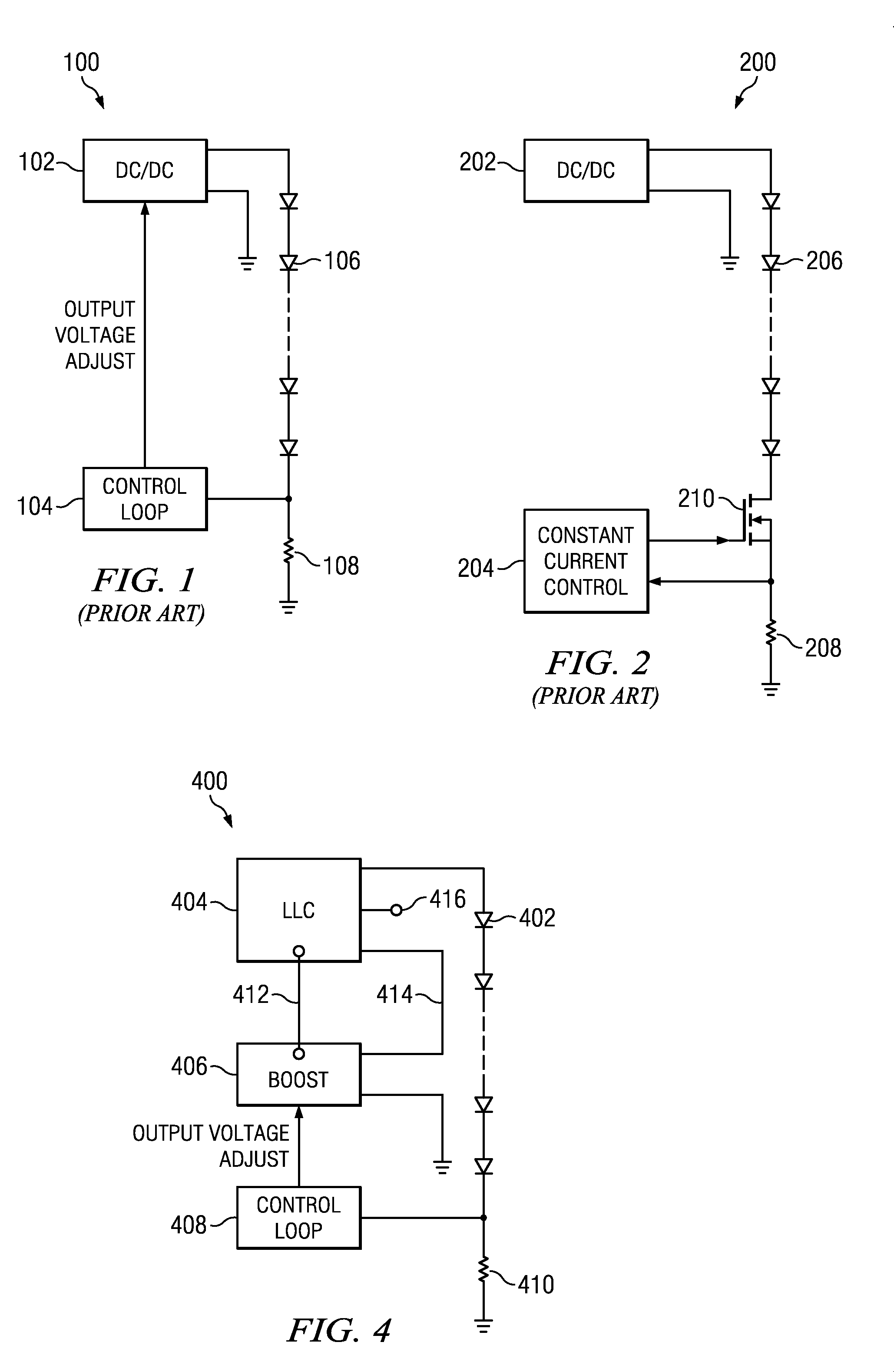
Therefore, it is not possible to merely supply a constant voltage across the string in order to maintain the current through the string constant.
This method is less efficient than the circuit shown in FIG. 1, because of the power dissipated in transistor 210.
In view of the fact that the DC-DC converter 202 always operates at the same voltage, current control takes place by dissipating the excess voltage, thus wasting power.
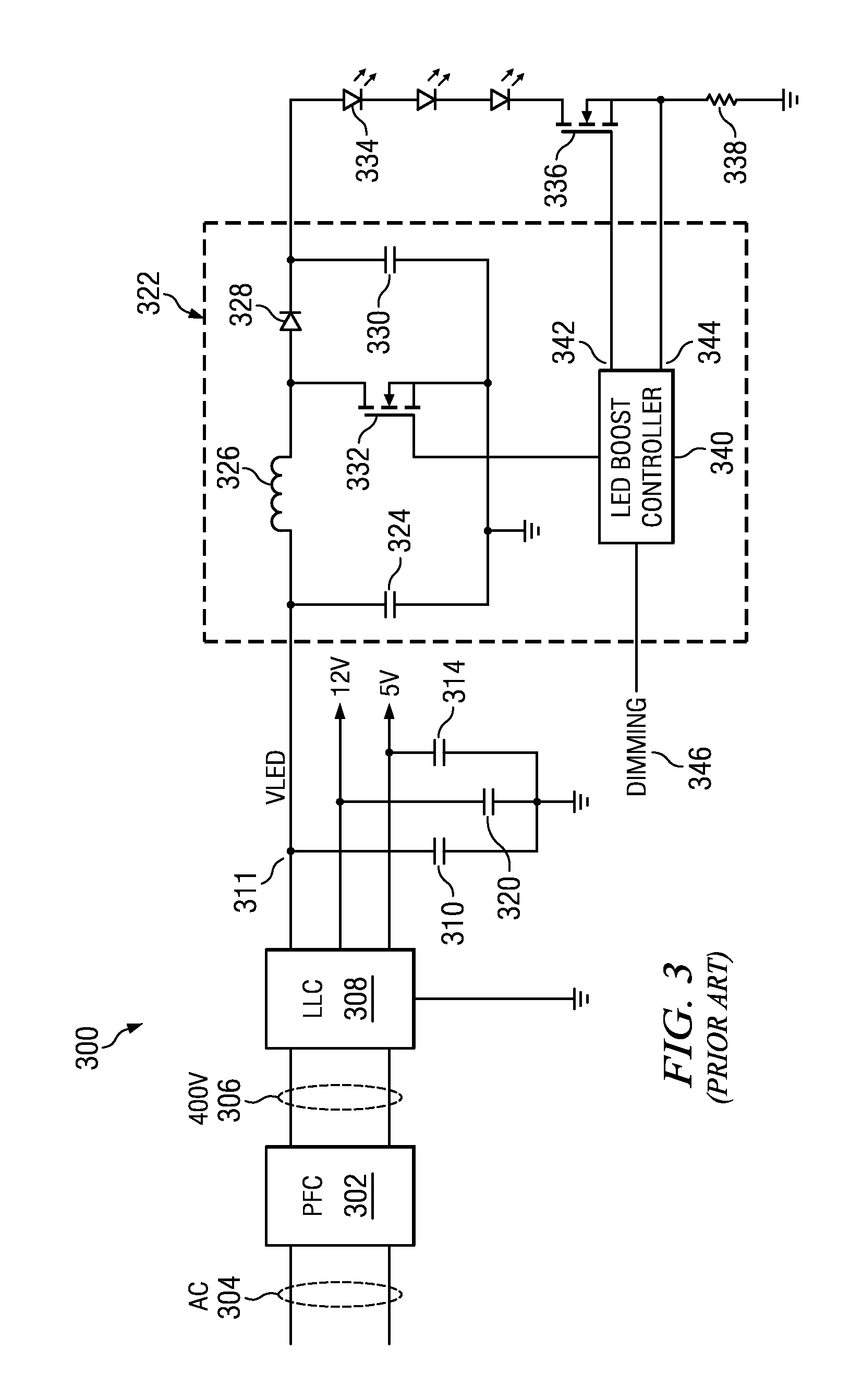
A disadvantage of this circuit is that the boost converter processes the entire power required by the LED string, which reduces the efficiency because the entire power has been processed.
In addition, because the boost converter is handling the full voltage and current of the LED output, the cost of the circuitry is increased because high-voltage components are required.
This also results in a larger inductor size due to the high output voltage.
The switching losses are higher because higher voltage components and results in a limitation on the maximum switching frequency, which in turn increases the inductor size and cost.

Method used


Image

  • LED driver with boost converter current control
  • LED driver with boost converter current control
  • LED driver with boost converter current control

Examples


Embodiment Construction

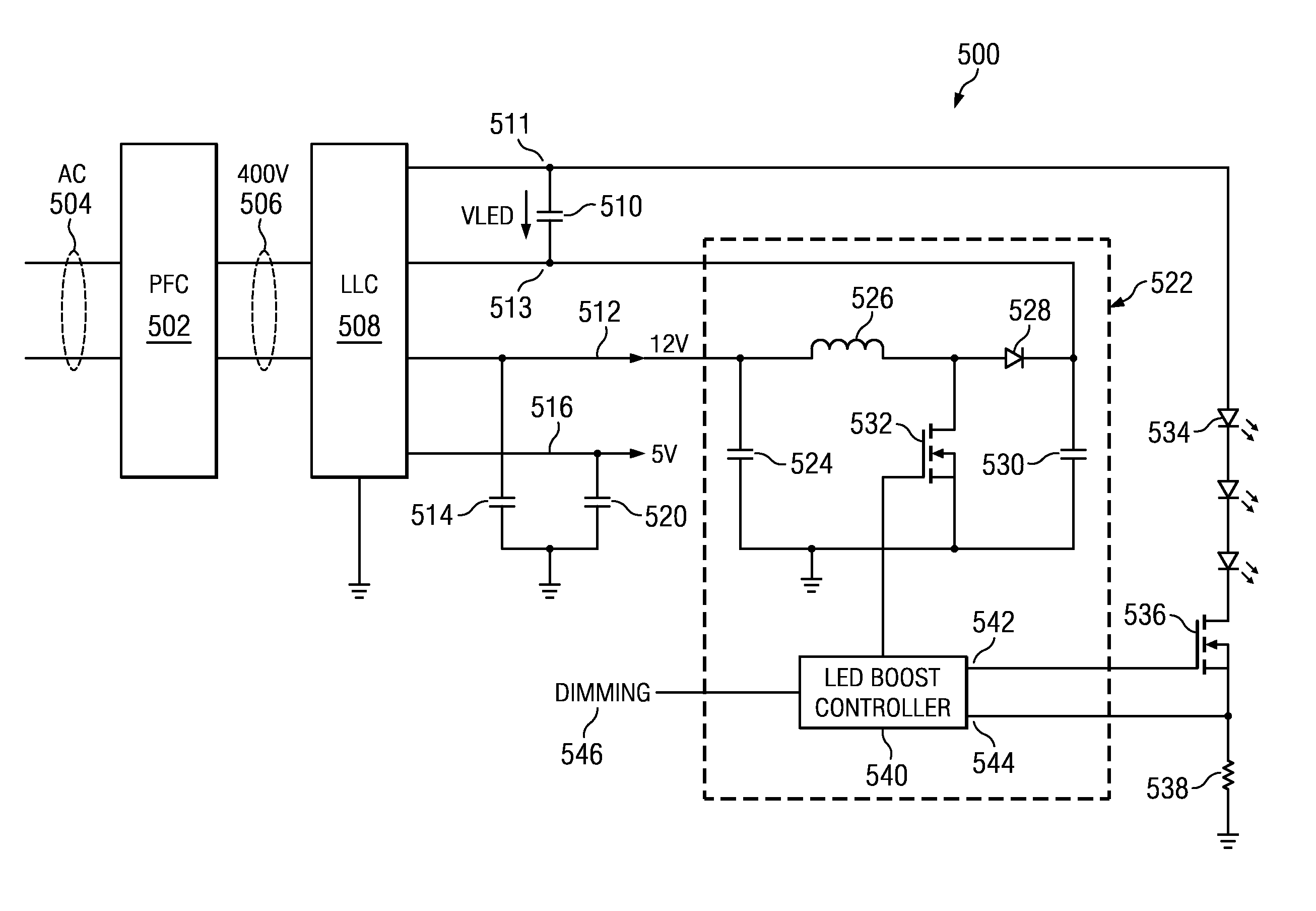
[0018]FIG. 4 shows a simplified block diagram of a first embodiment of the present invention, generally as 400. In FIG. 4, the LLC DC-DC converter 404 provides an output to operate the series string of LEDs 402. A resistor 410 is in series with the LEDs 402 and provides a voltage proportional to the current through the LEDs. A boost DC-DC converter 406 is coupled to receive an input voltage 412 which is one of the plurality of outputs 412, 416 from the DC-DC converter 404, and which are at a much lower voltage than that provided to the LED string 402. The optional auxiliary output 416 can be used to drive other circuitry, such as an audio amplifier, for example. The boost converter 406 provides an output at 414 which adds to the output voltage of the DC-DC converter 404 to provide the voltage for LED string 402. This additional voltage is used to control the current through the LED string 402. The voltage received by the boost converter 406 through input 412 is referred to ground. A...


PUM

PropertyMeasurementUnit
voltageaaaaaaaaaa
voltagesaaaaaaaaaa
currentaaaaaaaaaa

Abstract

An electronic circuit includes a driver for an LED light, having an isolated DC-DC converter having a first output at a higher voltage referred to a floating ground and a second output at a lower voltage than said first output and referred to a reference voltage. A DC-DC boost converter receives its input power from the second output of the isolated DC-DC converter and having its output coupled to the floating ground, whereby an output voltage to a LED light receives the sum of the voltages of the first output of the isolated DC-DC converter and the output of the DC-DC boost converter.

Description

FIELD OF THE INVENTION[0001]The invention relates to an LED driver, and more specifically, to a driver for a string of LEDsBACKGROUND OF THE INVENTION[0002]LED lighting is becoming very popular to replace incandescent lighting and fluorescent or compact fluorescent (CFL) lighting for area lighting, and more specifically, for the backlighting for LCD televisions, also known as LED televisions. In order to achieve the desired brightness and to maintain the spectrum characteristics of the LED, the current through the LED is controlled to be constant. Therefore, multiple LEDs are normally connected in a series string in order to maintain a constant current through all of the LEDs. The LEDs brightness can then be adjusted through pulse width modulation in order to dim the light output of the LEDs while maintaining the correct color spectrum. As is well known, the forward voltage drop of an LED varies from device to device, with age and with temperature. Therefore, it is not possible to m...

Claims


Application Information

Patent Timeline
Patent Type & Authority Applications(United States)
IPC IPC(8): H05B37/02H02J1/00G02F1/13357
CPCH05B45/38H02J1/00Y02B20/30H05B45/39H05B45/385
Inventor LU, BING
Owner TEXAS INSTR INC
Learn More