Check patentability & draft patents in minutes with Patsnap Eureka AI!

Setting radio frequency (RF) beamformer antenna weights per data-stream in a multiple-input-multiple-output (MIMO) system

Inactive Publication Date: 2014-02-20
MAGNOLIA BROADLAND INC
View PDF1 Cites 4 Cited by
  • Summary
  • Abstract
  • Description
  • Claims
  • Application Information

AI Technical Summary

Benefits of technology

The present invention addresses the challenge of selecting the phases in the receive antennas coupled to beamformers in a hybrid MIMO RDN architecture. The invention provides methods to maximize the signal for each data stream individually or collectively, by tuning the receive antennas based on the channel estimation information and the knowledge of pre-coding weight. The phase settings for all receive antennas can be obtained for each beamformer-data stream mapping configuration. The invention also provides a method to select the optimal beamformer-data stream mapping configuration based on maximizing the total received power or minimizing the ratio of maximum to minimum singular values of the transmission matrix. The invention also suggests using a switch matrix to pool the receive antennas among beamformers and applying the optimization computation to the pooled antenna configurations to improve the overall MIMO capacity.

Problems solved by technology

This is achieved by combining elements in the array in such a way that signals at particular angles experience constructive interference while others experience destructive interference.

Method used


Image

  • Setting radio frequency (RF) beamformer antenna weights per data-stream in a multiple-input-multiple-output (MIMO) system
  • Setting radio frequency (RF) beamformer antenna weights per data-stream in a multiple-input-multiple-output (MIMO) system
  • Setting radio frequency (RF) beamformer antenna weights per data-stream in a multiple-input-multiple-output (MIMO) system

Examples


first embodiment

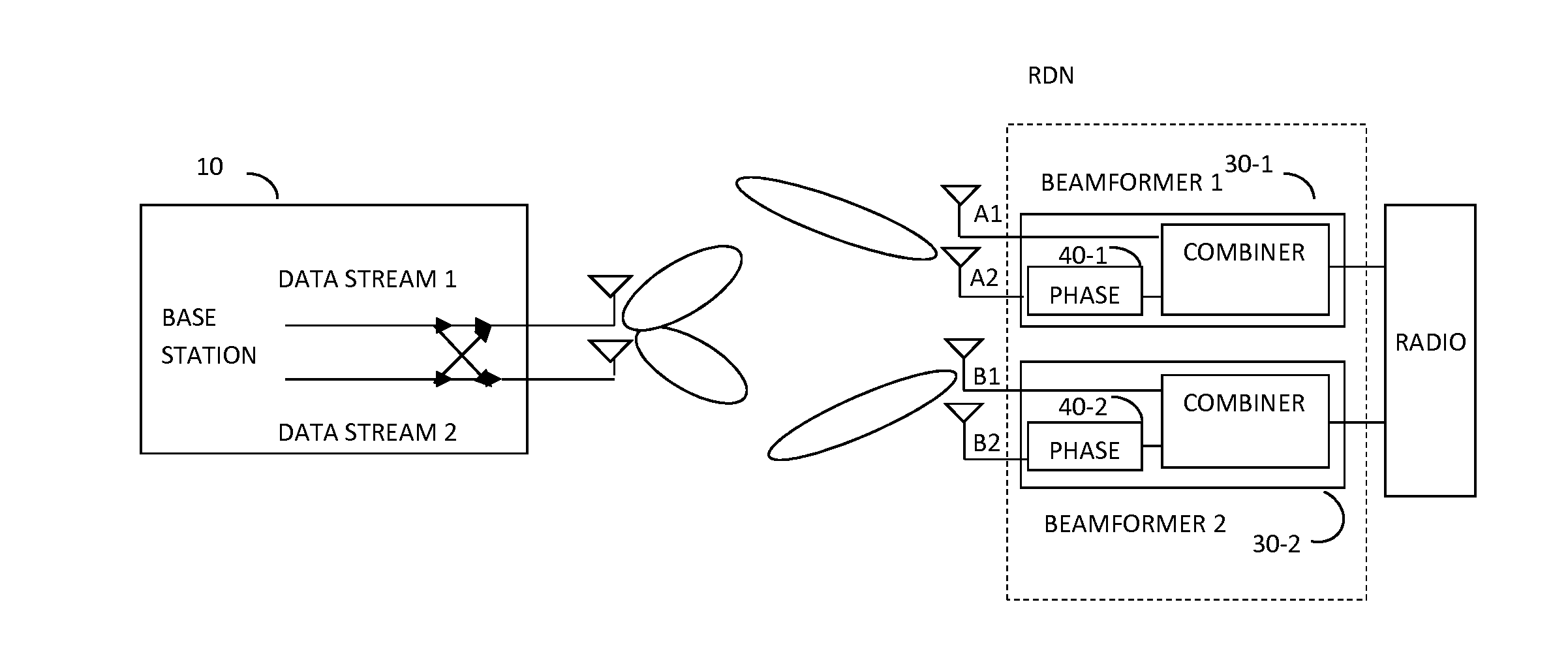
[0031]According to the present invention, the phases for receive antennae are selected and set such that each beamformer maximizes the received power for one particular data stream (e.g., beamformer 1, 2 . . .and N to maximize the received power for data stream 1, 2, . . . and N, respectively), and select other phases to configure different beamformer-data stream mapping (e.g., beamformer 1, 2, . . . and N maps to data stream N, 1, 2, . . . and N−1, respectively) by using the known pre-coding weight, and channel estimation from “look through”.

second embodiment

[0032]According to the present invention, the mapping configuration that maximizes the total received power of all data streams, or maximizes the SINR, may be selected or chosen from the mapping configurations. Phases are then set according to the selected configuration;

third embodiment

[0033]According the present invention, the condition of the transmission matrix for all beamformer-data stream mapping configurations (i.e., cond(transmission matrix), is checked. This condition is defined as the ratio of the maximum singular value to the minimum singular value of the transmission matrix, which represents the uniformity of the channel gains). If all the configurations experience relatively non-uniform channel gains, then the configuration that have the most uniform channel gains (i.e., minimum cond(transmission matrix)) is selected. On the other hand, a pool of configurations that have cond(transmission matrix) all below a pre-set threshold (e.g., 2), may be found. The configuration from the pool that maximizes the total received power of all data streams may be selected from the pool and the phases are set accordingly to optimize the overall performance (e.g., total capacity) for the MIMO system augmented with an Rx RDN.


PUM


Abstract

A system and a closed form method of optimizing a set of receive beamformers' weights, each feeding one of N multi-layer MIMO receiving system wherein the beamformers have a pool of M receive antennas wherein M is greater than N. Each beamformer is tuned to optimize one data stream, where selection of antennas per beamformer may be done out of a pool of antennas, and mapping of a given beamformer to a data stream is optimized per certain performance metrics

Description

CROSS-REFERENCE TO RELATED APPLICATIONS[0001]This application is a continuation-in-part application of U.S. patent application Ser. No. 13 / 630,146, filed on Sep. 28, 2012, which claims the benefit of U.S. Provisional Patent Application No. 61 / 652,743, filed on May 29, 2012, U.S. Provisional Patent Application No. 61 / 657,999, filed on Jun. 11, 2012, U.S. Provisional Patent Application No. 61 / 658,015, filed on Jun. 11, 2012, and U.S. Provisional Patent Application No. 61 / 665,592, filed on Jun. 28, 2012, all of which are incorporated herein by reference in their entirety.FIELD OF THE INVENTION[0002]The present invention relates generally to the field of radio frequency (RF) multiple-input-multiple-output (MIMO) systems and more particularly to systems and methods for RF MIMO systems using RF beamforming and / or digital signal processing, to augment the receiver performance.BACKGROUND OF THE INVENTION[0003]Prior to setting forth a short discussion of the related art, it may be helpful to...

Claims


Application Information

Patent Timeline
IPC IPC(8): H04B7/08
CPCH04B7/086H04B7/0417H04B7/0874
Inventor WANG, SHERWIN J.CHEN, PHIL F.
Owner MAGNOLIA BROADLAND INC
Features
  • R&D
  • Intellectual Property
  • Life Sciences
  • Materials
  • Tech Scout
  • Unparalleled Data Quality
  • Higher Quality Content
  • 60% Fewer Hallucinations
Learn More