Creep life management system for a turbine engine and method of operating the same

a technology of life management system and turbine engine, which is applied in the direction of machines/engines, nuclear elements, instruments, etc., can solve the problems of small material variation in the material properties of blades and buckets, difficult detection, and expenditure of resources

Active Publication Date: 2014-02-20
GENERAL ELECTRIC CO
View PDF3 Cites 47 Cited by
  • Summary
  • Abstract
  • Description
  • Claims
  • Application Information

AI Technical Summary

Problems solved by technology

However, slight material variations in the blades' and buckets' material properties may be present and are difficult to detect.
As a result, components having little or no defects may be processed with a similar expenditure of resources as those components having significant defects, including unnecessary replacement.
Also, at least some known maintenance repair processes for turbomachine components may include uncertainties of results for inspections that include standard non-destructive examination (NDE) and subsequent data analysis.
For example, many known NDE processes / analyses do not provide adequate correlations of crack-growth data, including crack-growth rates, as a function of creep and creep-fatigue.
In addition, there are few, if any, mechanisms to characterize crack-growth rates to specific components.
Therefore, it is difficult to determine a RUL of a component undergoing progressive creep.
Record keeping practices are not standardized and frequently, due to uncertainties regarding original dimensions of the components and subsequent measurements, accurate determinations of creep are difficult to make.
These systems typically require extensive wiring, modifications to the blades and buckets to accommodate the wiring, and complicated slip ring configurations, that are necessary due to the rotational operation of the monitored components, to transmit measurement data from the blades and buckets to an external data storage and analysis unit.
Therefore, such systems increase construction and maintenance costs.

Method used


Image

  • Creep life management system for a turbine engine and method of operating the same
  • Creep life management system for a turbine engine and method of operating the same
  • Creep life management system for a turbine engine and method of operating the same

Examples


Embodiment Construction

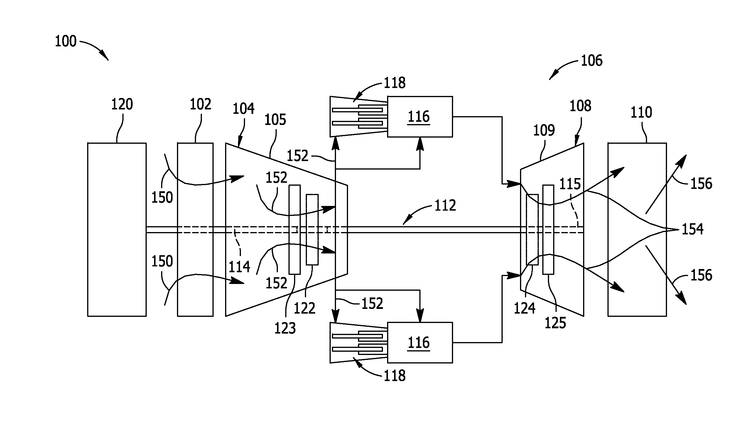
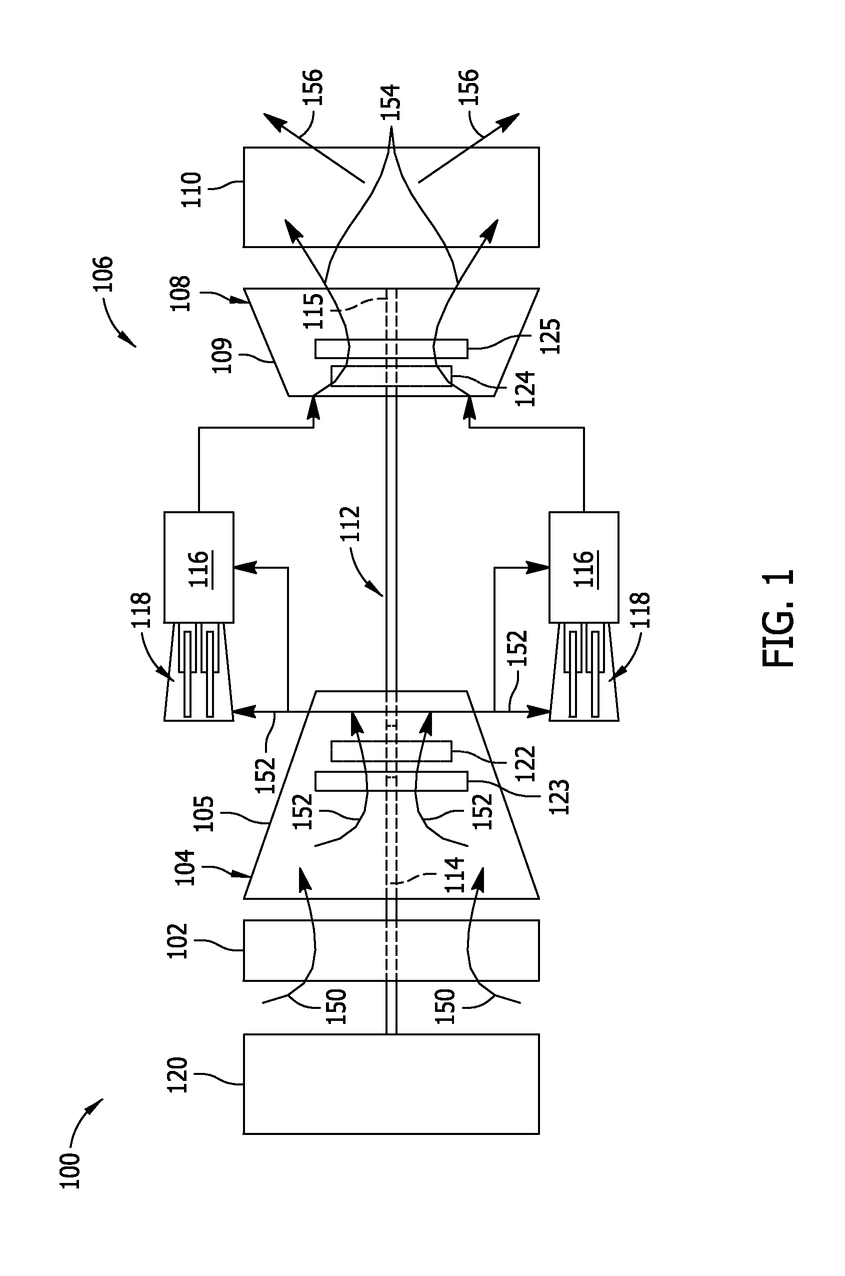
[0020]FIG. 1 is a schematic view of a rotary machine 100, i.e., a turbomachine, and more specifically, a turbine engine. In the exemplary embodiment, turbine engine 100 is a gas turbine engine. Alternatively, turbine engine 100 is any other turbine engine and / or rotary machine, including, without limitation, a steam turbine engine. In the exemplary embodiment, gas turbine engine 100 includes an air intake section 102, and a compressor section 104 that is coupled downstream from, and in flow communication with, intake section 102. Compressor section 104 is enclosed within a compressor casing 105. A combustor section 106 is coupled downstream from, and in flow communication with, compressor section 104, and a turbine section 108 is coupled downstream from, and in flow communication with, combustor section 106. Turbine engine 100 is enclosed within a turbine casing 109 and includes an exhaust section 110 that is downstream from turbine section 108. Moreover, in the exemplary embodiment...


PUM


Abstract

A creep life management system includes at least one sensor apparatus coupled to a first component. The at least one sensor apparatus is configured with a unique identifier. The creep life management system also includes at least one reader unit coupled to a second component. The at least one reader unit is configured to transmit an interrogation request signal to the at least one sensor apparatus and receive a measurement response signal transmitted from the at least one sensor apparatus. The creep life management system further includes at least one processor programmed to determine a real-time creep profile of the first component as a function of the measurement response signal transmitted from the at least one sensor apparatus.

Description

STATEMENT REGARDING FEDERALLY SPONSORED RESEARCH & DEVELOPMENT[0001]This invention was made with Government support under contract number DE-FC26-05NT42643 awarded by the Department of Energy (DOE). The Government has certain rights in this invention.BACKGROUND OF THE INVENTION[0002]The embodiments described herein relate generally to condition monitoring of systems and equipment, and more particularly, to a method and system for use in condition monitoring of turbomachines.[0003]At least some known turbomachines, i.e., gas turbine engines compress air via a plurality of rotatable compressor blades and ignite a fuel-air mixture in a combustor to generate combustion gases that are channeled through rotatable turbine buckets via a hot gas path. Also, at least some other known turbomachines, i.e., steam turbine engines channel steam through rotatable buckets via a steam path. Such known turbomachines convert thermal energy of the combustion gas stream and steam to mechanical energy use...

Claims


Application Information

Patent Timeline
Patent Type & Authority Applications(United States)
IPC IPC(8): G06F15/00
CPCG01M15/14F01D17/04F01D21/003F05D2270/332F05D2270/808G01N2203/0071G01N2203/0244
Inventor TRALSHAWALA, NILESHMILLER, HAROLD EDWARDBADAMI, VIVEK VENUGOPALVITTAL, SAMEERSEXTON, DANIEL WHITE
Owner GENERAL ELECTRIC CO
Why Eureka
Try Eureka