Battery testing system with energy circulation

a testing system and battery technology, applied in the field of battery testing system with energy circulation, can solve the problems of increasing ambient temperature, serious waste of energy, and failure to meet the power requirement of batteries, and achieve the effect of prolonging the service life of electric power storage modules

Inactive Publication Date: 2014-02-27
NAT CHUNG SHAN INST SCI & TECH
View PDF5 Cites 21 Cited by
  • Summary
  • Abstract
  • Description
  • Claims
  • Application Information

AI Technical Summary

Benefits of technology

[0006]Therefore, it is a primary objective of the present invention to overcome the shortcomings of the prior art by providing a battery testing system with energy circulation and capable of extending the life of an electric power storage module, wherein the electric power storage module has a total electric power capacity equal to a multiple of the total electric power capacity of the battery module to be tested, so that the state of charge of the electric power storage module can be set to a neighborhood near 70% and 30% in order to charge the state of charge of the battery module to be tested to 100%, and if the battery module to be tested is discharged by a current of 1 C, the full charge capacity of the electric power storage module is charged by a current much smaller than 1 C. As to the electric power storage module, if the state of charge has not reached 100%-0%, and the charging current is much smaller than 1 C, the rise of the operating temperature is much smaller than that at the state of charge reaching 100%-0% and the charging current equal to 1 C. Therefore, the present invention can achieve the effect of providing an electric power storage module with a smaller temperature rise which can extend the service life of the electric power storage module.

Problems solved by technology

If the full charge capacity drops below a specific standard such as a drop to a level below 70%, such battery may fail to satisfy the power requirement and must be discarded.
During the discharge, all discharged energies are consumed by the loader and converted into heat energy, and thus giving rise to a serious waste of energy and an increase of ambient temperature which may affect the precision of calibrating the state of charge.

Method used


Image

  • Battery testing system with energy circulation
  • Battery testing system with energy circulation
  • Battery testing system with energy circulation

Examples


Embodiment Construction

[0016]The technical characteristics of the present invention will become apparent with the detailed description of the preferred embodiments accompanied with the illustration of related drawings as follows. It is noteworthy that same numerals are used for representing the same respective elements in the drawings, and the drawings are provided for the purpose of illustrating the invention, but not intended for limiting the scope of the invention.

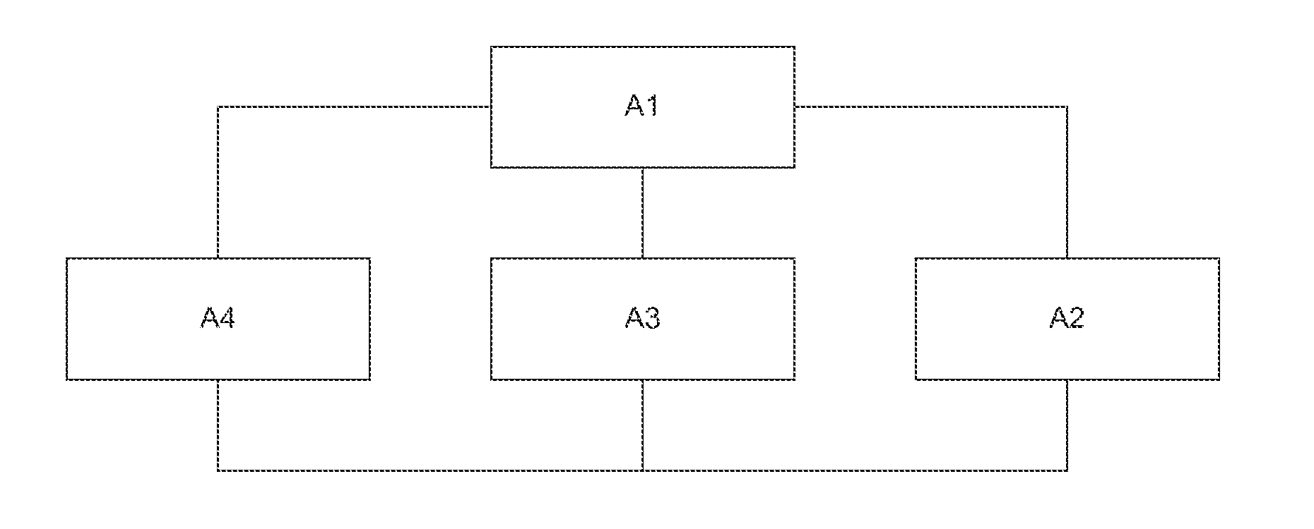
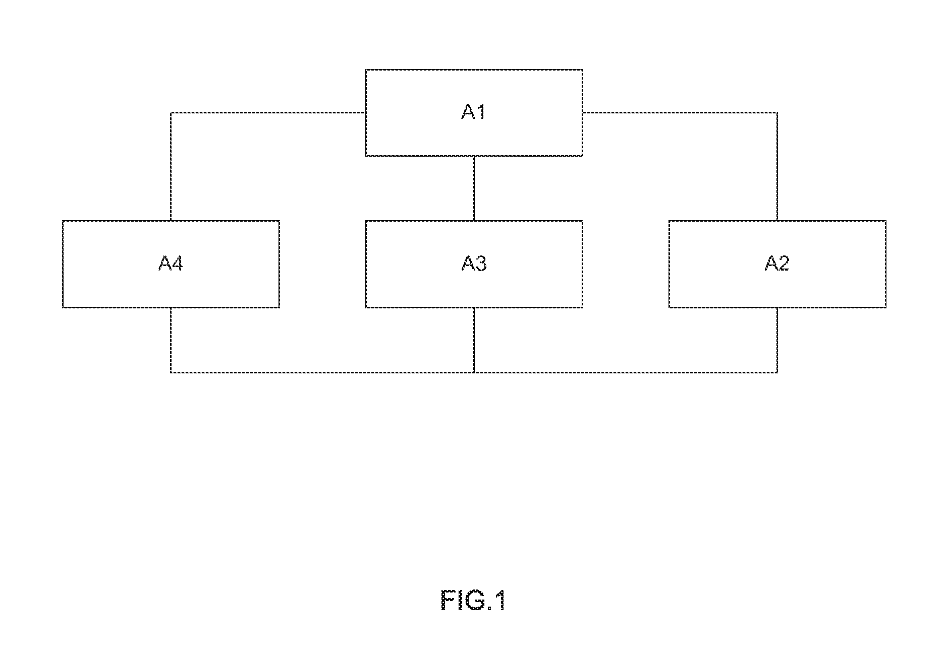
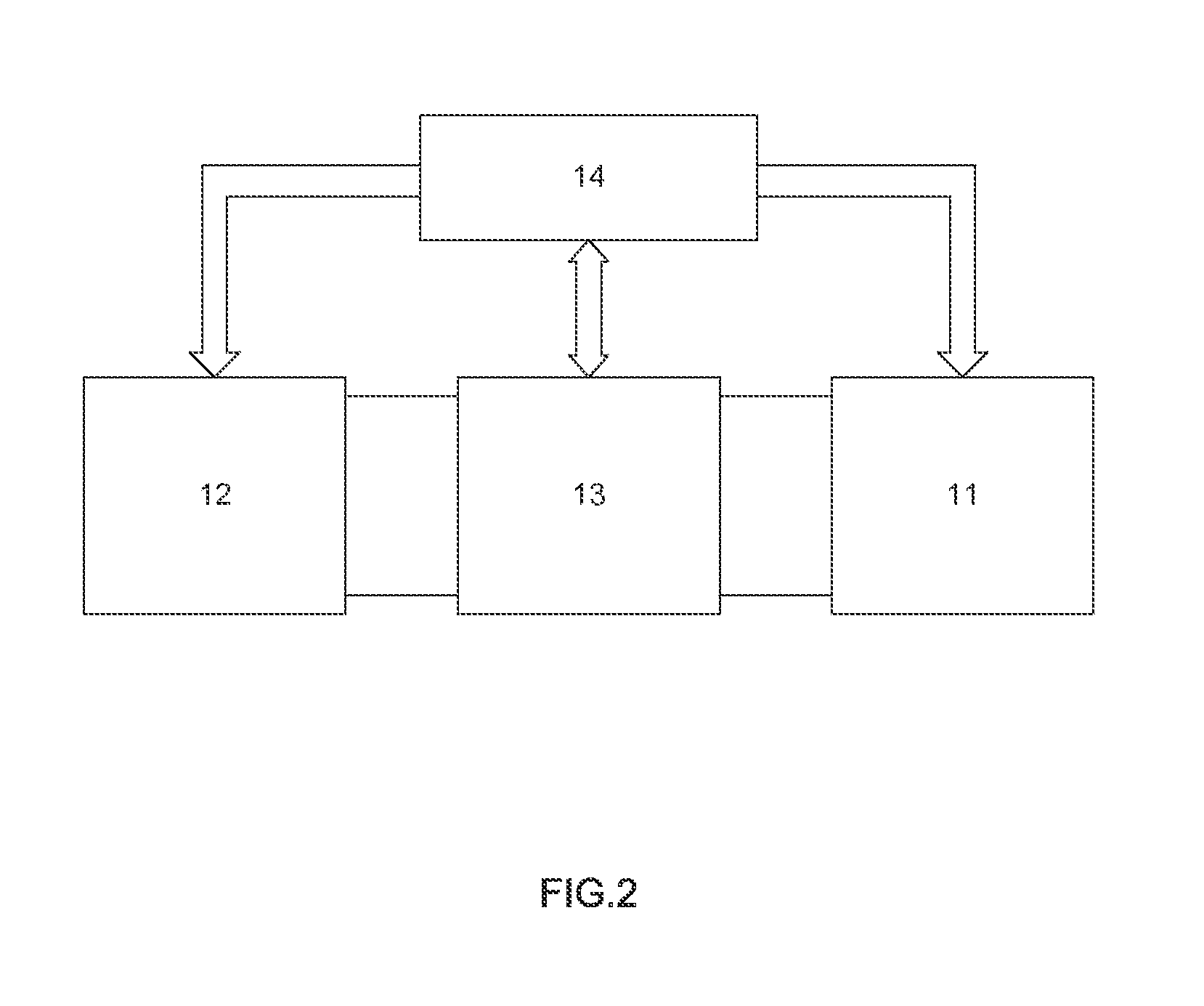
[0017]With reference to FIG. 2 for the major components of a battery testing system with energy circulation in accordance with a first preferred embodiment of the present invention, the battery testing system comprises a battery module to be tested 11; an electric power storage module 12, with a total electric power capacity equal to of a multiple of the total electric power capacity the battery module to be tested 11; a first bi-directional conversion module 13, electrically coupled to the battery module to be tested 11 and the electric powe...


PUM


Abstract

A battery testing system with energy circulation includes a battery module to be tested, an electric power storage module, a bi-directional conversion module and a control module, and the control module controls the bi-directional conversion module to discharge the electric power storage module and charge the battery module to be tested, or discharge the battery module to be tested and charge the electric power storage module, so that the electricity can be fully and repeatedly used, and the electric power storage module can use a second-used power battery to save the cost of the electric power storage module while the battery testing system can be isolated from the grid of utility power to avoid creating a burden to the grid of the utility power.

Description

FIELD OF THE INVENTION[0001]The present invention relates to a battery testing system with energy circulation, in particular to the battery testing system used for calibrating the state of charge to achieve the effects of testing the state of charge of a battery by a second-used power battery, and improving the life of the second-used power battery.BACKGROUND OF THE INVENTION[0002]For energy saving and carbon reduction, the power source of a car is developed with a hybrid or even a purely electric car design, wherein the electric car such as an electric bus, an electric car, an electric motorcycle and any other electric transportation means requires a power battery with a large capacity to substitute the power source of petrochemical fuels, so that the power battery will be mass produced and tested according to the market requirements. After being used for a while, the power battery will be aged and its full charge capacity (FCC) will drop. If the full charge capacity drops below a ...

Claims


Application Information

Patent Timeline
Patent Type & Authority Applications(United States)
IPC IPC(8): G01R31/36
CPCG01R31/385G01R31/387
Inventor SHIEH, FA-HWALIU, MING-LUNLIN, YOU-RONGLIH, WEN-CHENLIAO, YU-MIN
Owner NAT CHUNG SHAN INST SCI & TECH
Why Eureka
Try Eureka