Apparatus and method for operating a real time large diopter range sequential wavefront sensor

a wavefront sensor and diopter range technology, applied in the field of wavefront sensors, can solve the problems of complex data processing algorithms, wavefront sensors cannot take full advantage of lock-in detection schemes to provide higher signal to noise ratio, and cannot employ simple algorithms to quickly derive wavefront aberration, so as to achieve maximum signal-to-noise ratio, reduce electronic noise, and maintain amplifier stability without reducing the gain-bandwidth product

Inactive Publication Date: 2014-02-27
CLARITY MEDICAL SYST
View PDF2 Cites 46 Cited by
  • Summary
  • Abstract
  • Description
  • Claims
  • Application Information

AI Technical Summary

Benefits of technology

[0008]Another embodiment of the disclosure is to use a composite amplifier with a high impedance feedback resistor as part of the transimpedance amplifier to maximize signal-to-noise ratio, reduce electronic noise, and maintain amplifier stability without reducing gain-bandwidth product.

Problems solved by technology

These wavefront sensors generally use a CCD or CMOS image sensor to capture the wavefront data and need to use relatively complicated data processing algorithms to figure out the wavefront aberrations.
Due to the fact that a CCD or CMOS image sensor generally has a limited number of gray scales and cannot be operated at a frame rate well above the 1 / f noise range, these wavefront sensors therefore cannot take full advantage of lock-in detection scheme to provide higher signal to noise ratio.
They cannot employ a simple algorithm to quickly derive the wavefront aberration.
As a result, when these wavefront sensors are integrated with an ophthalmic device such as a surgical microscope, they generally cannot provide accurate / repeatable real time wavefront aberration measurement, especially with the microscope's illumination light turned on.

Method used


Image

  • Apparatus and method for operating a real time large diopter range sequential wavefront sensor
  • Apparatus and method for operating a real time large diopter range sequential wavefront sensor
  • Apparatus and method for operating a real time large diopter range sequential wavefront sensor

Examples


Embodiment Construction

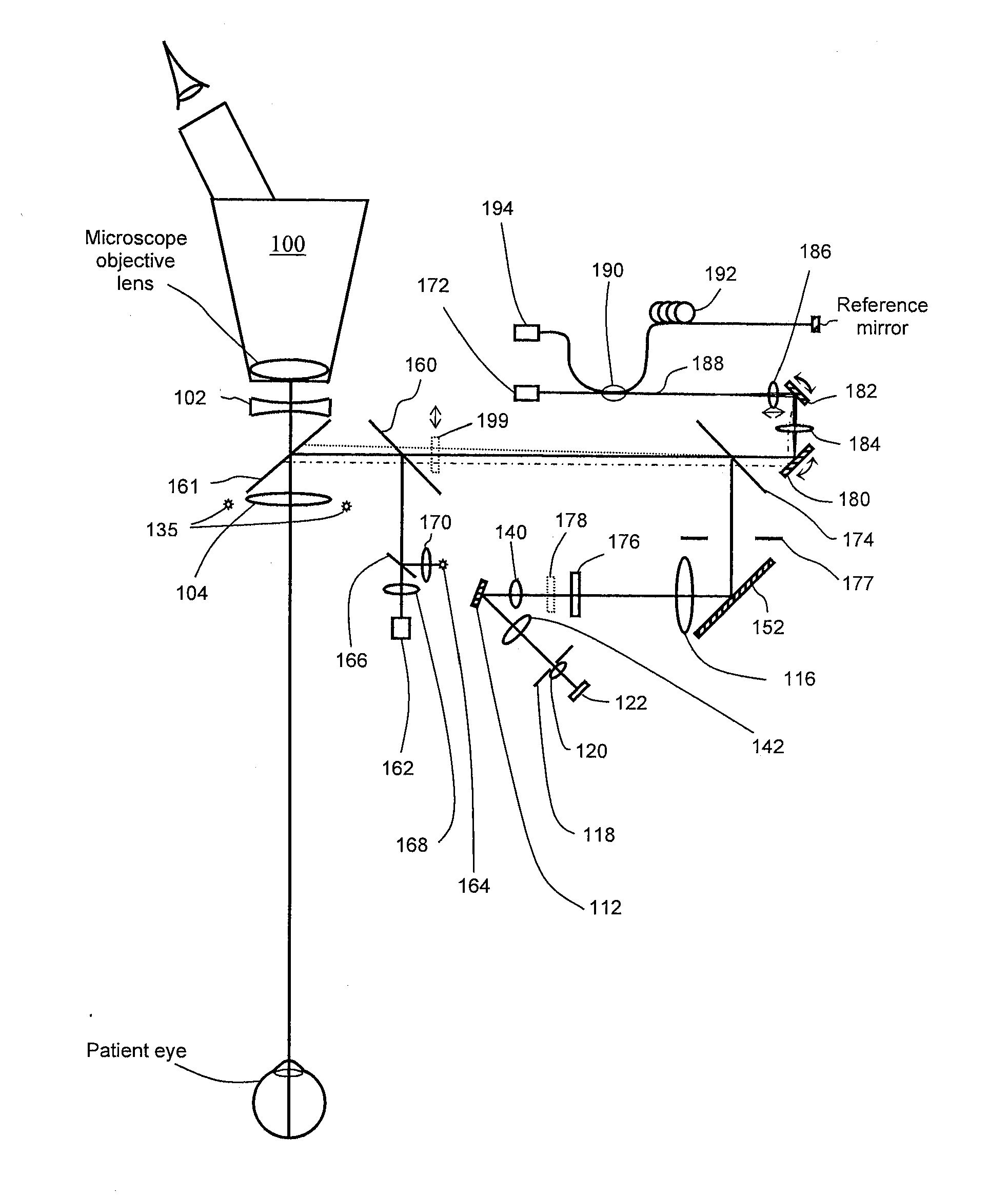
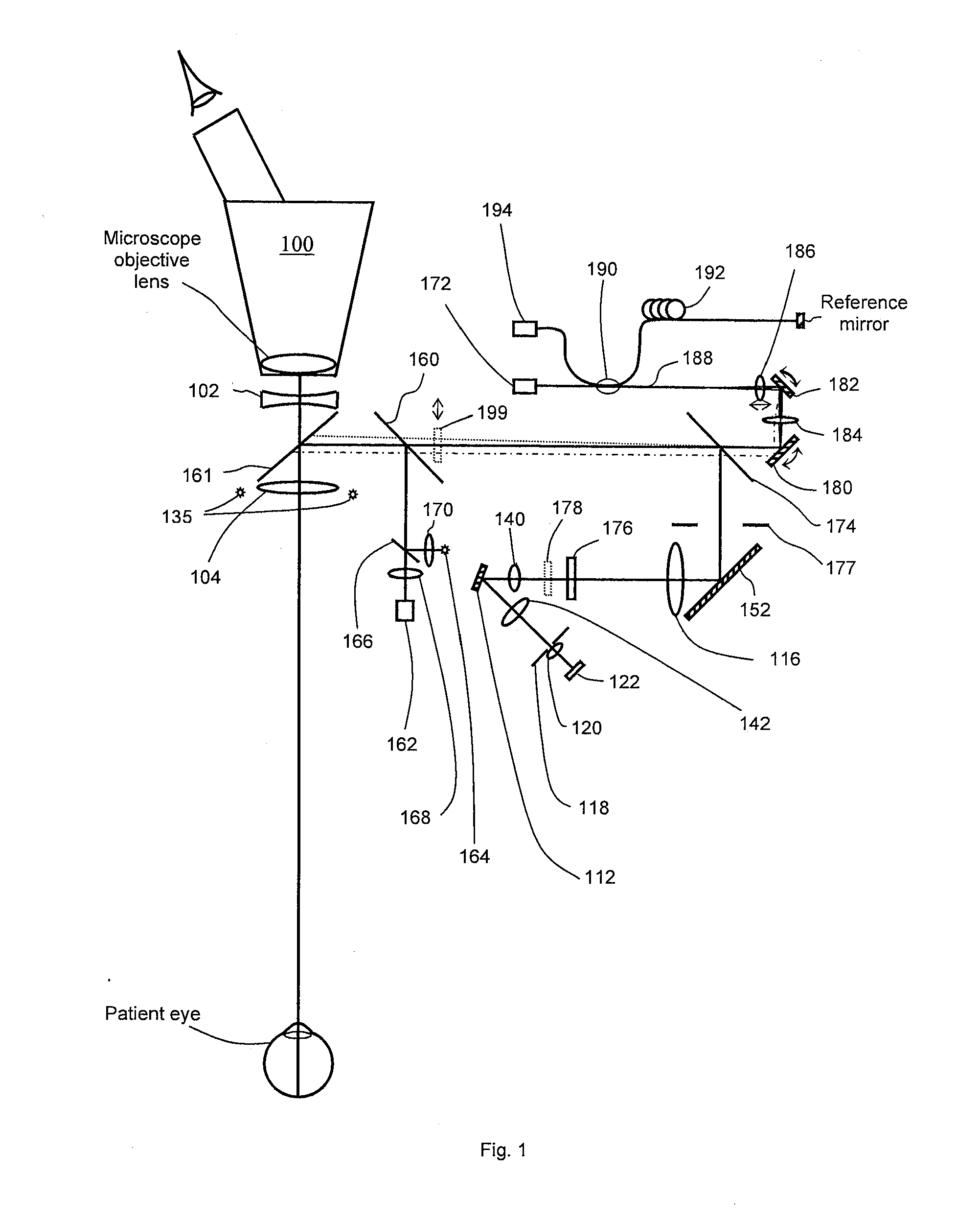
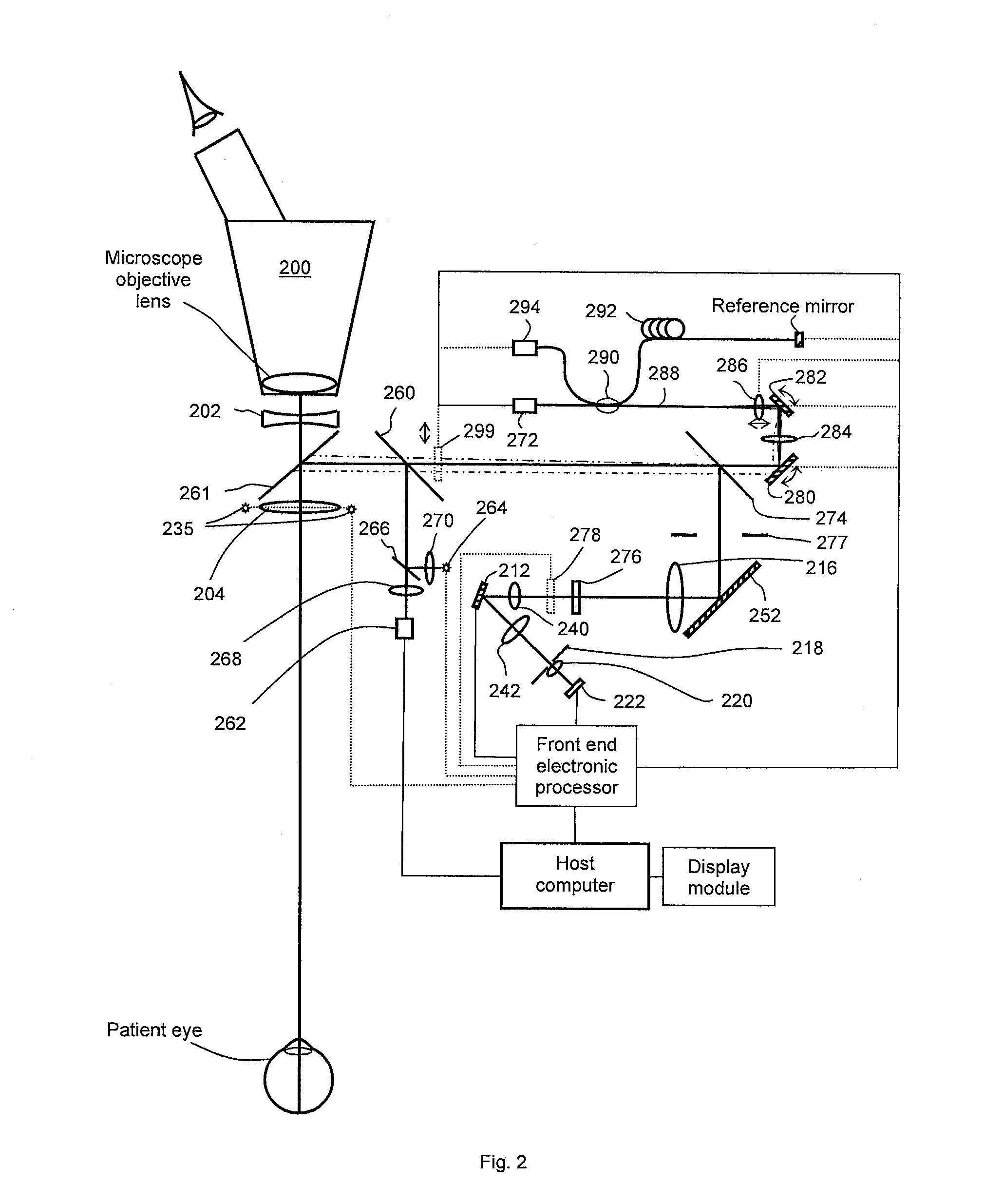
[0048]Reference will now be made in detail to various embodiments of the invention. Examples of these embodiments are illustrated in the accompanying drawings. While the invention will be described in conjunction with these embodiments, it will be understood that it is not intended to limit the invention to any embodiment. On the contrary, it is intended to cover alternatives, modifications, and equivalents as may be included within the spirit and scope of the invention as defined by the appended claims. In the following description, numerous specific details are set forth in order to provide a thorough understanding of the various embodiments. However, the present invention may be practiced without some or all of these specific details. In other instances, well known process operations have not been described in detail in order not to unnecessarily obscure nor apply limitations to the present invention. Further, each appearance of the phrase an “example embodiment” at various place...


PUM


Abstract

A sequential wavefront sensor includes a light source, a beam deflecting element, a position sensing detector configured to output a plurality of output signals and a plurality of composite transimpedance amplifiers each coupled to receive an output signal. The output of each composite transimpedance amplifier is phase-locked to a light source drive signal and a beam deflecting element drive signal.

Description

CROSS-REFERENCE TO RELATED APPLICATIONS[0001]This application is a continuation-in-part of U.S. application Ser. No. 13 / 745,738 filed Jan. 18, 2013, which is a continuation of U.S. application Ser. No. 13 / 198,442 filed Aug. 4, 2011 (now U.S. Pat. No. 8,356,900 issued Jan. 22, 2013), which is a continuation-in-part of U.S. application Ser. No. 12 / 790,301 filed May 28, 2010, which is a division of U.S. application Ser. No. 11 / 761,890 filed Jun. 12, 2007, (now U.S. Pat. No. 7,815,310 issued Oct. 19, 2010), which is a continuation-in-part of U.S. application Ser. No. 11 / 335,980 filed Jan. 20, 2006 (now U.S. Pat. No. 7,445,335 issued Nov. 4, 2008); this application is a continuation-in-part of U.S. application Ser. No. 13 / 902,716 filed May 24, 2013, which is a continuation of U.S. application Ser. No. 13 / 354,763 filed Jan. 20, 2012, (now U.S. Pat. No. 8,454,162 issued Jun. 4, 2013), which is a continuation of U.S. application Ser. No. 12 / 605,219 filed Oct. 23, 2009, (now U.S. Pat. No. 8,...

Claims


Application Information

Patent Timeline
Patent Type & Authority Applications(United States)
IPC IPC(8): A61B3/10
CPCA61B3/1015G01J9/00G01J1/0414G01J1/0437A61F2009/00848A61B3/132A61B3/14A61B3/152A61B3/102G01J2003/064A61B3/1035A61B3/112A61B3/113A61B3/0025
Inventor ZHOU, YANCHEW, BRADFORDSHEA, WILLIAM
Owner CLARITY MEDICAL SYST
Why Eureka
Try Eureka