Boom for construction machine

a construction machine and boom technology, applied in the field of booms for construction machines, can solve the problems of reducing the weight of the boom, the larger the entire boom gets, and the higher the cost of materials, so as to increase the joint strength and increase the joint strength

Inactive Publication Date: 2014-02-27
NIHON KENKI CO LTD
View PDF1 Cites 11 Cited by
  • Summary
  • Abstract
  • Description
  • Claims
  • Application Information

AI Technical Summary

Benefits of technology

[0018]With this arrangement, of the left and right web plates formed of the first to fifth web materials, between the second web materials, the first partition plate can be provided by being joined by welding so as to be located between the upper and lower flange plates, and, with the first partition plate, it is possible to increase the joint strength between the left and right web plates and the upper and lower flange plates by welding. On the other hand, of the left and right web plates, between the fourth web materials, the second partition plate can be provided by being joined by welding so as to be located between the upper and lower flange plates, and, with the second partition plate, it is possible to increase the joint strength between the left and right web plates and the upper and lower flange plates by welding.
[0019](5) The present invention adopts a configuration in which, an arm-side mounting member that is located on a front end side in a front-rear direction and is welded between the upper and lower flange plates is provided in the left and right web plates. This makes it possible to provide the arm-side mounting member between an area located on a front end side of the entire length of the left and right web plates and the upper and lower flange plates by joining the arm-side mounting member therebetween by welding and rotatably couple an arm to the distal end side of the boom with the arm-side mounting member.

Problems solved by technology

However, the thicker the plate materials forming the left and right web plates and the upper and lower flange plates get, the heavier the entire boom gets and the higher the cost of material gets.
In addition, this increases the inertial force when the boom is moved upward and downward by the boom cylinder, making it difficult to improve the positioning performance when the boom is stopped in a desired position.
Furthermore, since there is a need to use a large hydraulic cylinder as the boom cylinder, reducing the weight of the boom has become a great problem.

Method used


Image

  • Boom for construction machine
  • Boom for construction machine
  • Boom for construction machine

Examples


first embodiment

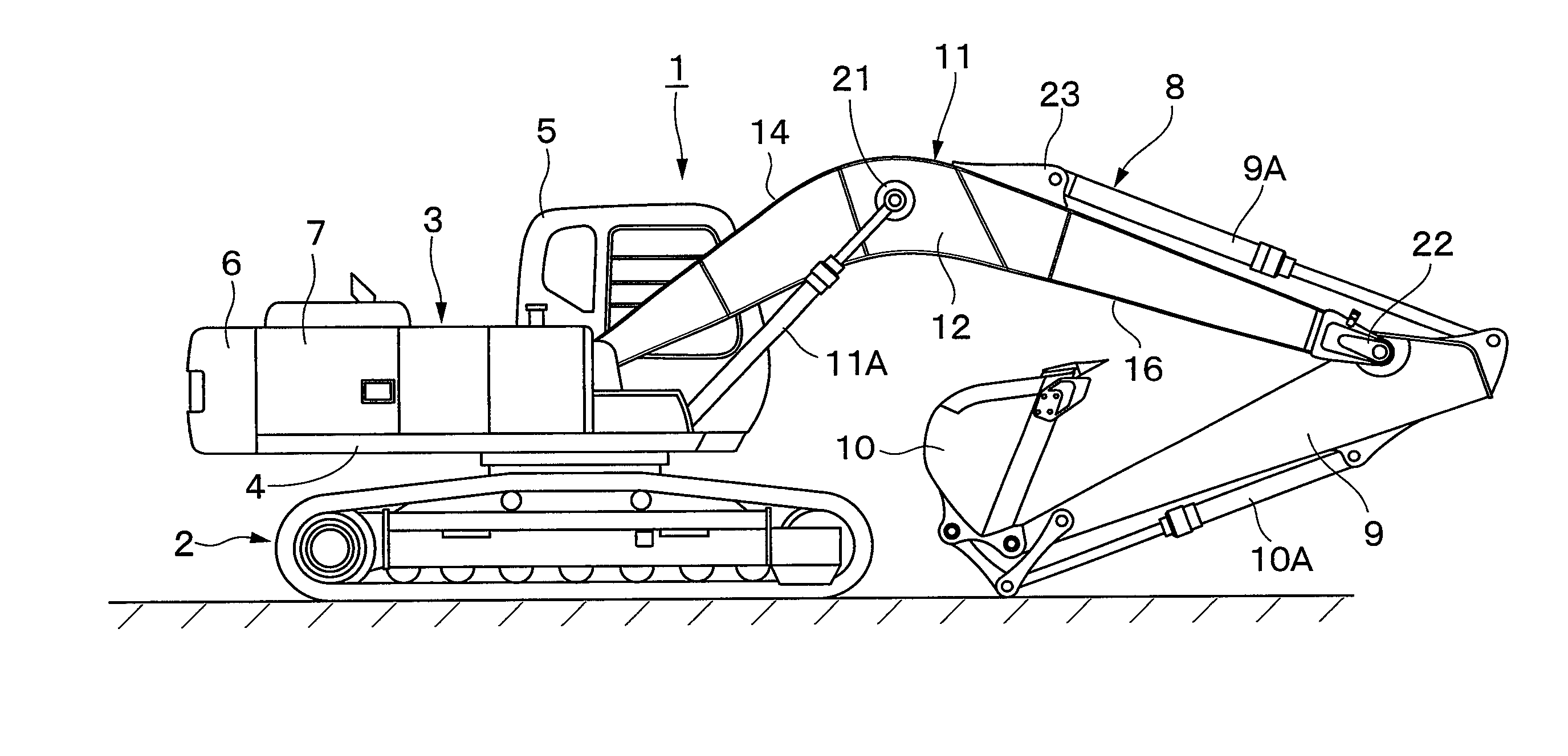
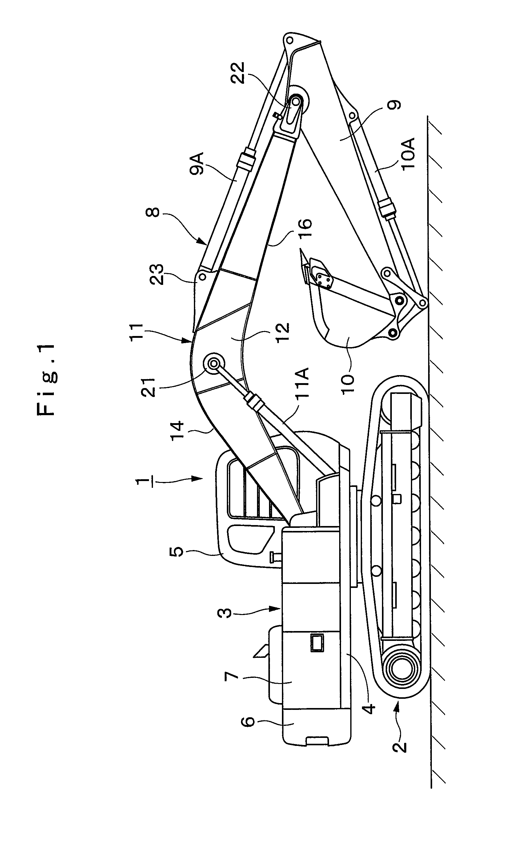
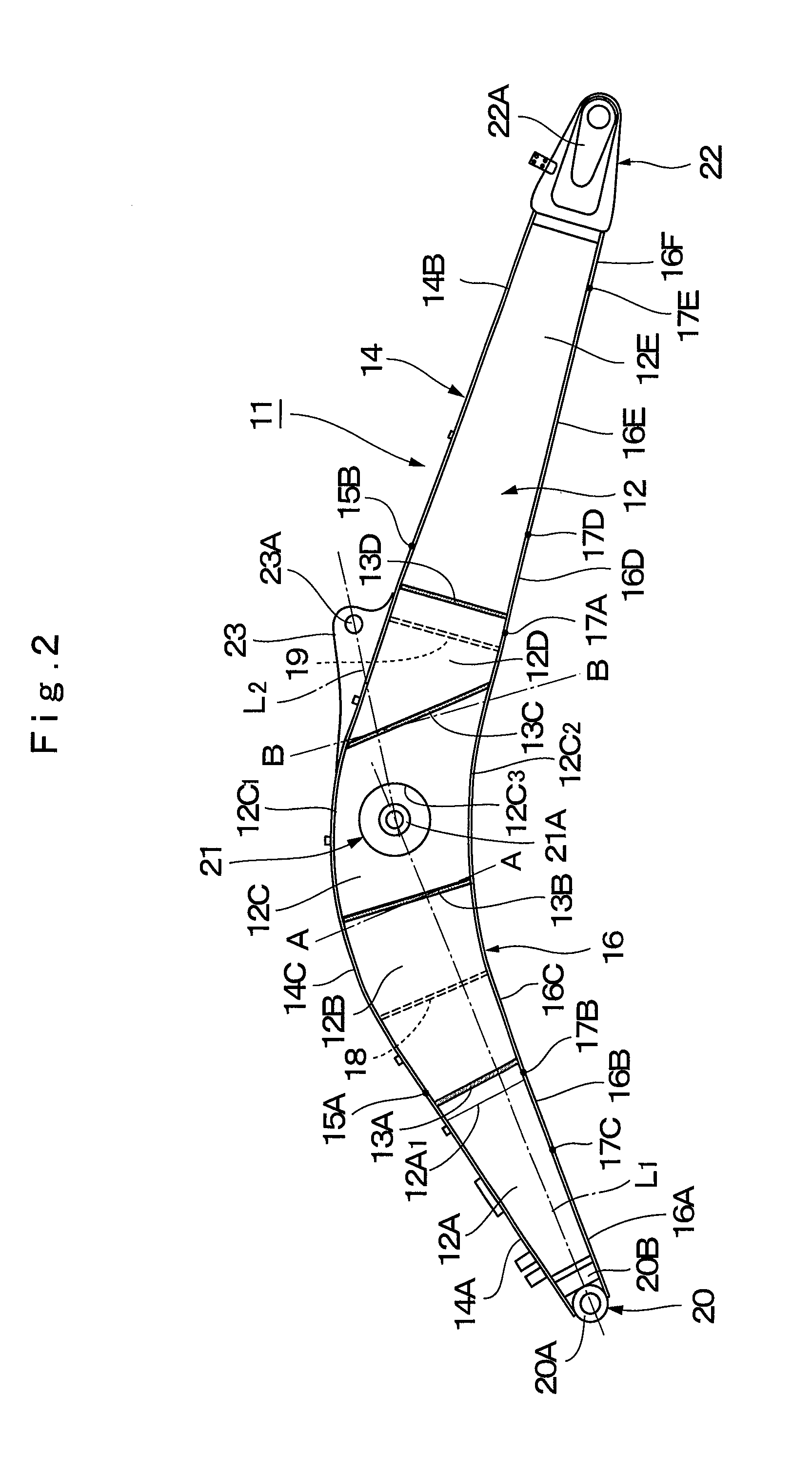
[0031]Here, FIGS. 1 to 9 show a boom of a hydraulic excavator according to the present invention.

[0032]In the drawings, designated at 1 is a hydraulic excavator as a construction machine, and, as shown in FIG. 1, the hydraulic excavator 1 is largely constituted by an automotive crawler-type lower traveling structure 2, an upper revolving structure 3 rotatably mounted on the lower traveling structure 2, and a working mechanism 8 which will be described later. The upper revolving structure 3 of the hydraulic excavator 1 forms a vehicle body of the construction machine with the lower traveling structure 2. The upper revolving structure 3 is formed of a revolving frame 4, a cab 5, a counterweight 6, a housing cover 7, and the like, which will be described later.

[0033]Indicated at 4 is the revolving frame forming a frame of the upper revolving structure 3, and the working mechanism 8 which will be described later is liftably attached on the front side of the revolving frame 4, and the co...

second embodiment

[0119]In the above-described second embodiment, it is explained by citing as an example the case in which the left and right web plates 42 are each formed of six plate materials, the upper flange plate 43 is formed of four plate materials, and the lower flange plate 44 is formed of seven plate materials. However, the present invention is not limited to the same; for example, the left and right web plates may be each formed of seven plate materials, the upper flange plate may be formed of three plate materials, and the lower flange plate may be formed of six plate materials. On the other hand, the left and right web plates may be each formed of five plate materials, the upper flange plate may be formed of four plate materials, for example, and the lower flange plate may be formed of six plate materials. Moreover, a configuration may be adopted in which the left and right web plates are each formed of five plate materials, the upper flange plate is formed of four plate materials, and ...


PUM


Abstract

In left and right web plates (12) of a boom (11), first to fifth web materials (12A to 12E) are joined at edge portions in a front-rear direction along welding lines (13A to 13D). In an upper flange plate (14), a rear upper flange material (14A), a front upper flange material (14B), and a middle upper flange material (14C) are joined at edge portions in a front-rear direction along welding lines (15A, 15B). Ina lower flange plate (16), first to sixth lower flange materials (16A to 16F) are joined at edge portions in a front-rear direction along welding lines (17A to 17E). The welding lines (13A to 13D) of the left and right web plates (12) are disposed in positions that are different from those of the welding lines (15A, 15B) of the upper flange plate (14) and the welding lines (17A to 17E) of the lower flange plate (16) in a front-rear direction. This makes it possible to reduce the entire weight and thereby achieve reduction in weight while ensuring bending strength, torsional strength, and the like of the boom (11).

Description

TECHNICAL FIELD[0001]The present invention relates to a boom for a construction machine, the boom suitably used, as a working arm, in a working mechanism of a hydraulic excavator, for example.BACKGROUND ART[0002]In general, a working mechanism provided in a construction machine such as a hydraulic excavator is formed of a boom that is coupled, at the base end side thereof, to a frame of a vehicle body side in such a way that the boom can move upward and downward, an arm that is rotatably coupled to the distal end side of the boom, a working tool such as an excavating bucket that is rotatably coupled to the distal end side of the arm, a boom cylinder, an arm cylinder, and a working tool cylinder that operate the boom, the arm, and the working tool, respectively.[0003]Of the working mechanism described above, the boom is formed as a box shape structural body formed of left and right web plates, an upper flange plate joined to the upper end sides of the left and right web plates by wel...

Claims


Application Information

Patent Timeline
Patent Type & Authority Applications(United States)
IPC IPC(8): E02F3/38
CPCE02F3/38
Inventor TAKAHASHI, TAKESHIHAMADA, ATSUSHISHIMODAIRA, TAKAYUKIYAMAMOTO, HIKARUSUGAYA, MAKOTO
Owner NIHON KENKI CO LTD
Why Eureka
Try Eureka