Artificial valve leaflet

a technology of artificial valves and leaflets, which is applied in the field of artificial valve leaflets, can solve the problems of difficulty in using stent artificial valves in juvenile patients whose replacements are carried out throughout the lifetime, and functional deterioration, so as to suppress deterioration or alteration of artificial valves, prevent deterioration of left heart function, and avoid mechanical stress.

Active Publication Date: 2014-02-27
WASEDA UNIV
View PDF3 Cites 1 Cited by
  • Summary
  • Abstract
  • Description
  • Claims
  • Application Information

AI Technical Summary

Benefits of technology

The present invention provides a stentless artificial mitral valve and leaflets that can function without using any stent, which helps to prevent complications and deterioration of heart functions after valve replacement. The valve can be easily implanted into the heart, has a simple configuration and can be manufactured with no fine adjustments. The use of the template of the present invention makes it easy to form the artificial valve leaflet.

Problems solved by technology

However, since the stent artificial valve deteriorates and alters with time, the artificial valve needs to be replaced at a relatively short period, resulting in a problem that it is difficult to use the stent artificial valve for juvenile patients for whom the number of replacements throughout the lifetime increases.
That is, since the first and second valve leaflets are joined to the stent in a complicated manner, mechanical stress caused by the opening / closing movement of the valve applies to the joints, which produces functional deterioration with time.
For this reason, after the valve replacement, the part of the papillary muscle remains to be resected, the strength of the wall of the left ventricle becomes smaller than before the surgery, which may produce deterioration the left heart function.
Furthermore, when manufacturing the stent artificial valve, the sheet-like first and second valve leaflets need to be joined to the surface of the stent which is three-dimensionally structured with wires in a complicated manner, which not only complicates the manufacturing process of the artificial valve but also requires fine positional adjustment when the first and second valve leaflets are joined so as to realize desired valve opening / closing movement, resulting in another problem that the artificial valve cannot be easily manufactured.
On the other hand, since the aforementioned stentless artificial valve has a rectilinear tubular outside shape, it is hard to be implanted into the heart, high-level manipulation is required for the medical doctor and application to infant patients having small-sized hearts is particularly difficult.
Furthermore, as in the case of the stent artificial valve, this stentless artificial valve may cause deterioration of the left heart functions after valve replacement.
Moreover, when manufacturing the stentless artificial valve, it is necessary to join the first and second valve leaflets to the inner surface of the rectilinear tube while performing fine positional adjustment so as to realize the desired valve opening / closing movement, resulting in a problem that the joining operation becomes more difficult than the stent artificial valve and the manufacturing process of the artificial valve becomes still more complicated.

Method used


Image

  • Artificial valve leaflet
  • Artificial valve leaflet
  • Artificial valve leaflet

Examples


Embodiment Construction

[0029]Hereinafter, an embodiment of the present invention will be described with reference to the accompanying drawings.

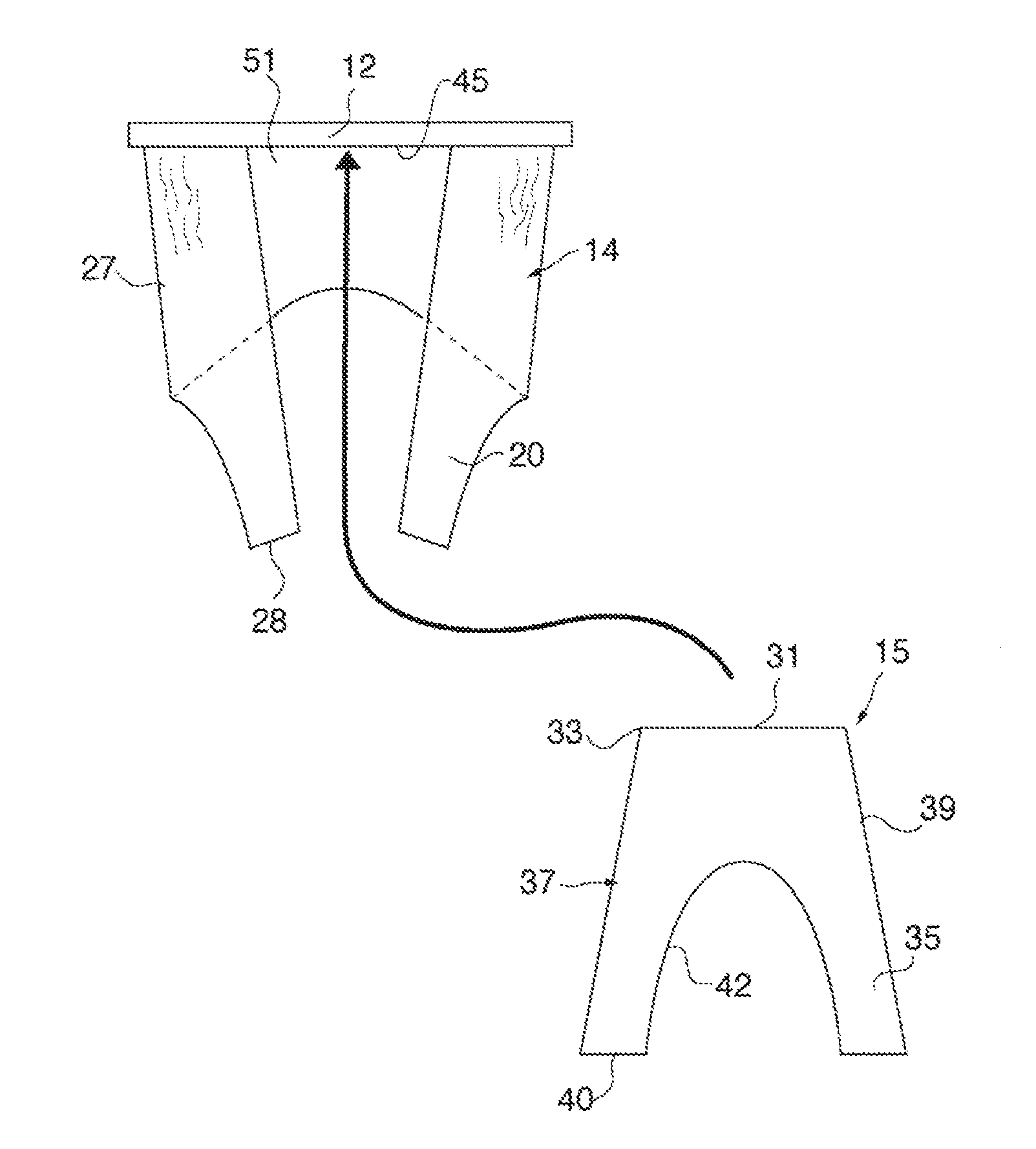
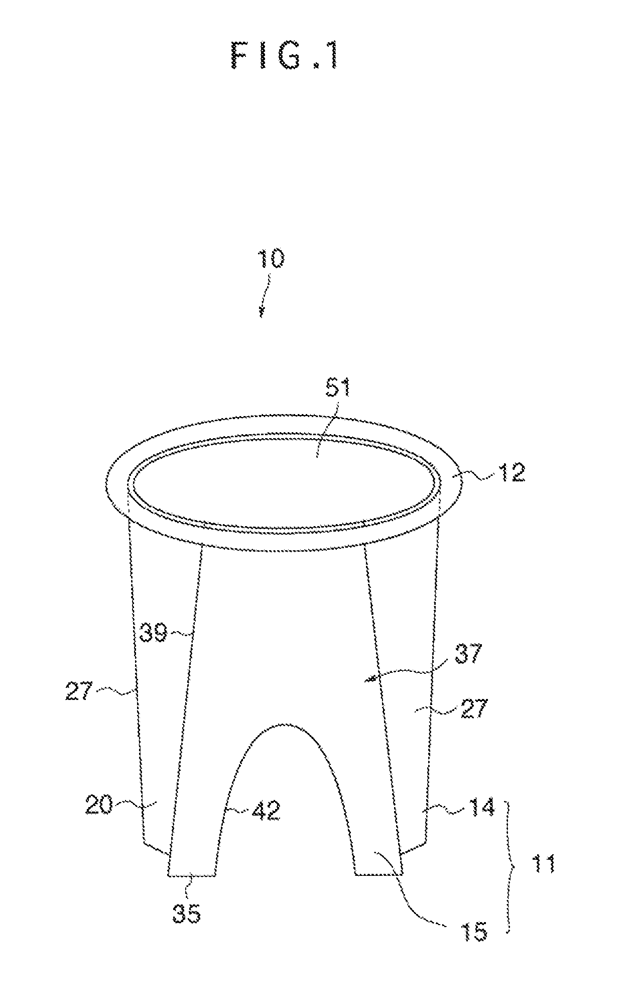
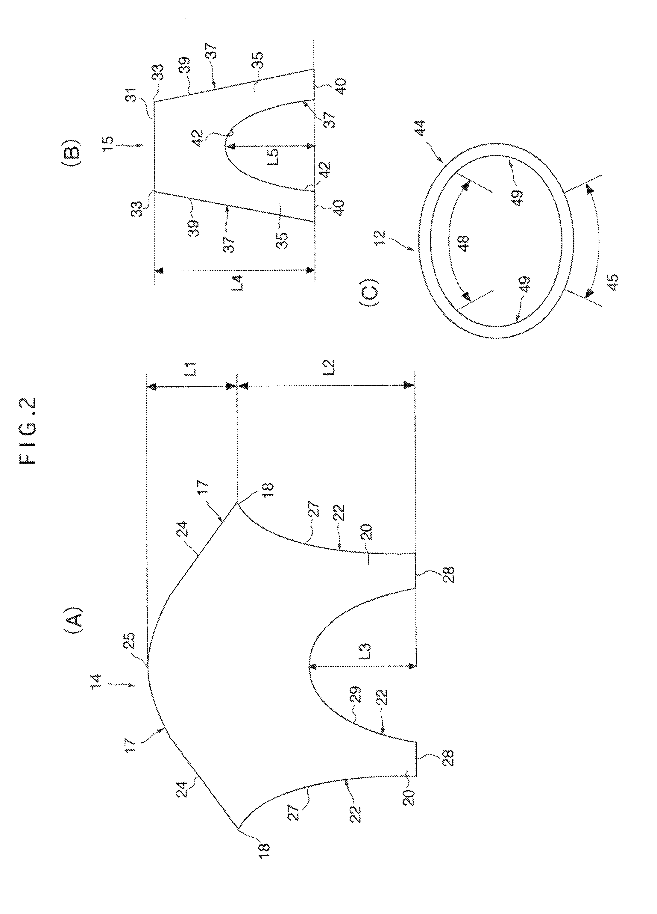
[0030]FIG. 1 shows a schematic perspective view of a stentless artificial mitral valve according to the present embodiment and FIG. 2 shows a schematic plan view of components of the stentless artificial mitral valve. In these FIGS, a stentless artificial mitral valve 10 is an artificial mitral valve capable of realizing valve behavior substantially equivalent to that of the mitral valve of the human body and has a bicuspidal valve structure made up of two valve leaflets. The stentless artificial mitral valve 10 is configured by including an artificial valve leaflet 11 having a shape corresponding to the anterior cusp and the posterior cusp of the mitral valve, and a ring 12 that supports the artificial valve leaflet 11.

[0031]The artificial valve leaflet 11 is made up of an anterior cusp forming member 14 and a posterior cusp forming member 15, which are each symme...


PUM


Abstract

An artificial mitral valve has a ring, an anterior cusp-side region, a posterior cusp-side region and a valve leaflet connected along an outer edge of the ring. The valve leaflet includes an anterior cusp forming member connected to the anterior cusp-side region and a posterior cusp forming member connected to the posterior cusp-side region. The anterior cusp forming member is provided with has an upper edge joined to the ring and a lower edge that forms a bifurcated portion. The upper edge is made up of a pair of right and left edges that incline inward and upward from the right and left sides, and a curved edge interposed between the inclined edges that curves along the anterior cusp-side region. The posterior cusp forming member has an upper edge joined to the ring and a lower edge that forms a bifurcated portion.

Description

CROSS-REFERENCE TO RELATED APPLICATIONS[0001]This application is a Divisional application of U.S. patent application Ser. No. 13 / 177,183, filed Jul. 6, 2011, the entire contents of which are herein incorporated by reference.BACKGROUND OF THE INVENTION[0002]1. Field of the Invention[0003]The present invention relates to a stentless artificial mitral valve and artificial valve leaflet, and template and cutter for forming the artificial valve leaflet, and more particularly, to a stentless artificial mitral valve, and artificial valve leaflet which are implanted into the heart on the occasion of valve replacement for valvular disease of heart or the like, capable of realizing valve behavior similar to a real mitral valve.[0004]2. Description of the Related Art[0005]Of the human heart valves, the mitral valve is a unidirectional valve located between the left atrium into which the blood from the lung flows and the left ventricle that sends out the blood flown into the left atrium to the ...

Claims


Application Information

Patent Timeline
Patent Type & Authority Applications(United States)
IPC IPC(8): A61F2/24A61B17/32
CPCA61F2/2412A61B17/32A61F2/2415A61F2240/005A61F2250/0082
Inventor UMEZU, MITSUOKASEGAWA, HITOSHI
Owner WASEDA UNIV
Why Eureka
Try Eureka