Natural fracture injection test

a technology of injection test and natural fracture, which is applied in the field of natural fracture injection test, can solve the problems of degrading the value of the recorded data, and the recording data is damaged

Active Publication Date: 2014-02-27
BAKER HUGHES INC
View PDF6 Cites 21 Cited by
  • Summary
  • Abstract
  • Description
  • Claims
  • Application Information

AI Technical Summary

Benefits of technology

[0003]Disclosed is a method for estimating a property of an earth formation penetrated by a borehole. The method includes: performing a borehole integrity test at a pressure less than a fracture gradient pressure of the formation, the borehole integrity test providing leakage data; injecting a fluid into the formation at a first pressure greater than the fracture gradient pressure at a first flow rate during a first injection time interval using a fluid injector; measuring pressure versus time using a pressure sensor and a timer during a first test time interval after the injecting for the first injection time interval to provide first pressure data; injecting a fluid into the formation at a second flow rate greater than the first flow rate during a second injection time interval using the fluid injector; measuring pressure versus time using the pressure sensor and the timer during a second test time interval after the injecting for the second injection time interval to provide second pressure data; and estimating the property using the first pressure data, the second pressure data, and the leakage data.
[0004]Also disclosed is an apparatus for estimating a property of an earth formation penetrated by a borehole. The apparatus includes: a fluid injector configured to inject fluid through the borehole into the formation at a selected flow rate; a pressure sensor configured to sense pressure of a fluid in the borehole; a timer configured to measure a time interval; and a processor. The processor is configured to: receive leakage data from a borehole integrity test conducted at a pressure less than a fracture gradient pressure of the formation using the fluid injector; receive first pressure data having a pressure versus time measurement obtained using the pressure sensor and the timer during a first test time interval after injecting a fluid into the formation at a first pressure greater than the fracture gradient pressure at a first flow rate during a first injection time interval using the fluid injector; receive second pressure data having a pressure versus time measurement obtained using the pressure sensor and the timer during a second test time interval after injecting a fluid into the formation at a second flow rate greater than the first flow rate during a second injection time interval using the fluid injector; and estimate the property using the first pressure data, the second pressure data, and the leakage data.
[0005]Further disclosed is a non-transitory computer-readable medium having computer-executable instructions for estimating a property of an earth formation penetrated by a borehole by implementing a method that includes: receiving leakage data from a borehole integrity test conducted at a pressure less than a fracture gradient pressure of the formation using a fluid injector; receiving first pressure data having a pressure versus time measurement obtained using a pressure sensor and a timer during a first test time interval after injecting a fluid into the formation at a first pressure greater than the fracture gradient pressure at a first flow rate during a first injection time interval using the fluid injector; receiving second pressure data having a pressure versus time measurement obtained using the pressure sensor and the timer during a second test time interval after injecting a fluid into the formation at a second flow rate greater than the first flow rate during a second injection time interval using the fluid injector; and estimating the property using the first pressure data, the second pressure data, and the leakage data.

Problems solved by technology

In addition, temperature fluctuations over that time can corrupt the recorded data degrading its value.

Method used


Image

  • Natural fracture injection test
  • Natural fracture injection test
  • Natural fracture injection test

Examples


Embodiment Construction

[0011]A detailed description of one or more embodiments of the disclosed apparatus and method presented herein by way of exemplification and not limitation with reference to the Figures.

[0012]Disclosed are a method and apparatus for testing a formation of interest intended for hydraulic stimulation. Results from testing may be used to select a hydraulic stimulation pressure and a formation permeability or injectivity that results from hydraulic stimulation at the selected pressure.

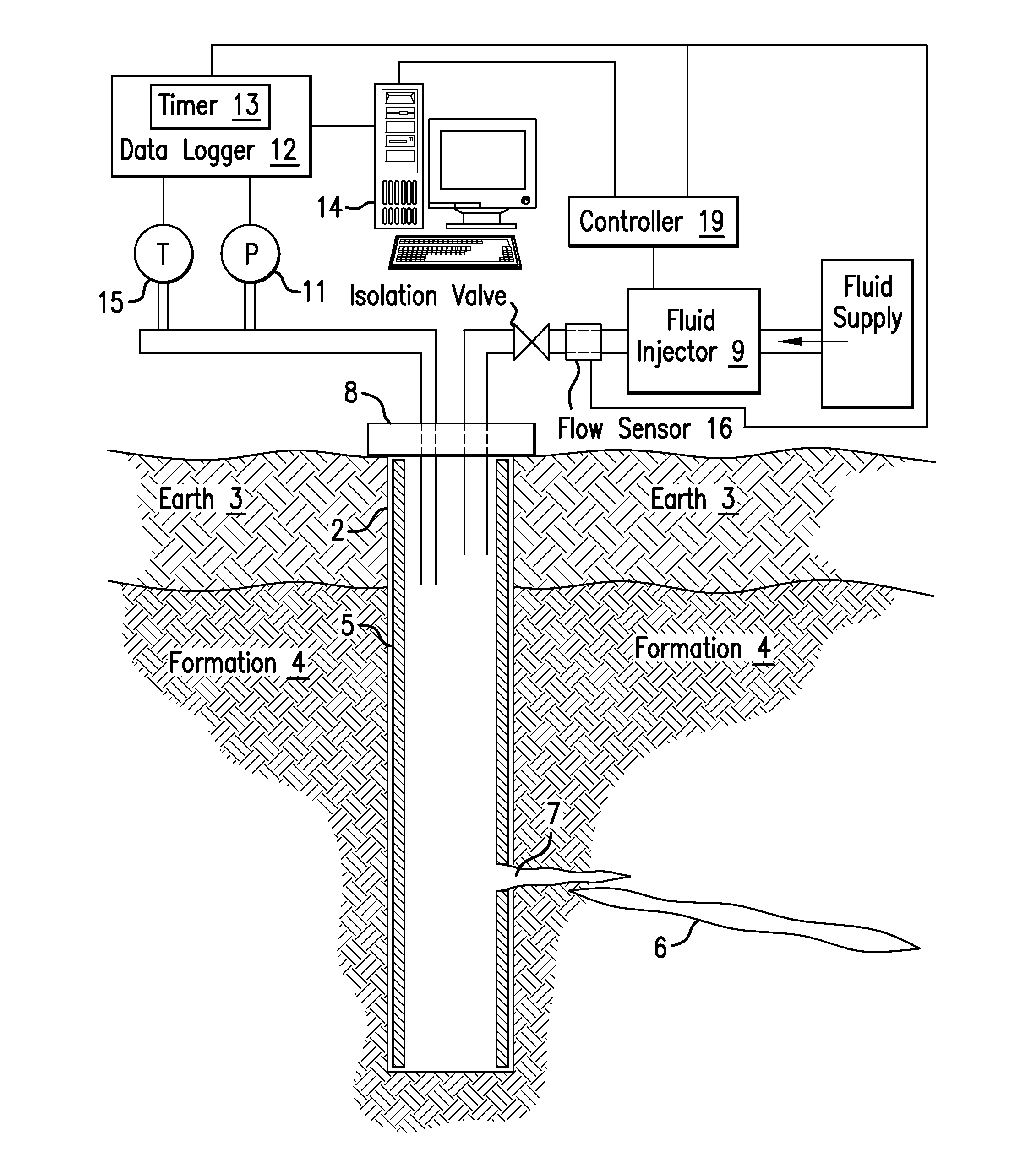
[0013]Reference may now be had to FIG. 1. FIG. 1 illustrates a cross-sectional view of an exemplary embodiment of a borehole 2 penetrating the earth 3, which includes an earth formation 4. The borehole 2 is lined with a casing 5. In other embodiments, the borehole 2 may be open or partially lined with the casing 5. The formation 4 includes a fracture 6. The fracture 6 has a vertical displacement having a wing that extends radially from the borehole 2. It can be appreciated that the formation 4 may include ...


PUM


Abstract

A method for estimating a property of an earth formation penetrated by a borehole includes: performing a borehole integrity test at a pressure less than a fracture gradient pressure of the formation to provide leakage data; injecting a fluid into the formation at a first pressure greater than the fracture gradient pressure during a first injection time interval using a fluid injector; measuring pressure versus time using a pressure sensor and a timer during a first test time interval to provide first pressure data; injecting a fluid into the formation at a second flow rate greater than the first flow rate during a second injection time interval using the fluid injector; measuring pressure versus time using the pressure sensor and the timer during a second test time interval to provide second pressure data; and estimating the property using the first pressure data, the second pressure data, and the leakage data.

Description

BACKGROUND[0001]Hydraulic stimulation is used to improve productivity of hydrocarbon formations. Hydraulic stimulation involves injecting a fluid into a geologic formation at a high enough pressure to open naturally occurring rock fractures to improve formation permeability. Performing hydraulic stimulation requires knowing the pressure to be applied to the fluid. In addition, an amount of expected increase in permeability is also required in order to determine if pursuing production will be cost effective.[0002]In order to obtain this information, a conventional pressure test is typically performed. This test involves applying a pressurized fluid to the formation of interest at an initial pressure and recording the pressure decay over time, which can take a week or longer. In nano-Darcy shale, the time can be on the order of months for only a slight pressure decay. In addition, temperature fluctuations over that time can corrupt the recorded data degrading its value. Hence, it woul...

Claims


Application Information

Patent Timeline
Patent Type & Authority Applications(United States)
IPC IPC(8): G01M3/04G06F19/00
CPCE21B47/06E21B49/008E21B43/26E21B49/08
Inventor ANDERSON, CHRISTOPHER RLMOOS, DANIELBARTON, COLLEEN A.
Owner BAKER HUGHES INC
Why Eureka
Try Eureka