Printing plates doped with release oil

a technology of printing plates and release oil, applied in the field of imaging members, can solve the problems of not being able to accommodate true high-speed variable data printing, not being able to create and print a new pattern from one page to the next, and the cost of permanently patterned imaging plates or cylinders is amortized over the number of copies

Active Publication Date: 2014-03-06
XEROX CORP
View PDF8 Cites 7 Cited by
  • Summary
  • Abstract
  • Description
  • Claims
  • Application Information

AI Technical Summary

Benefits of technology

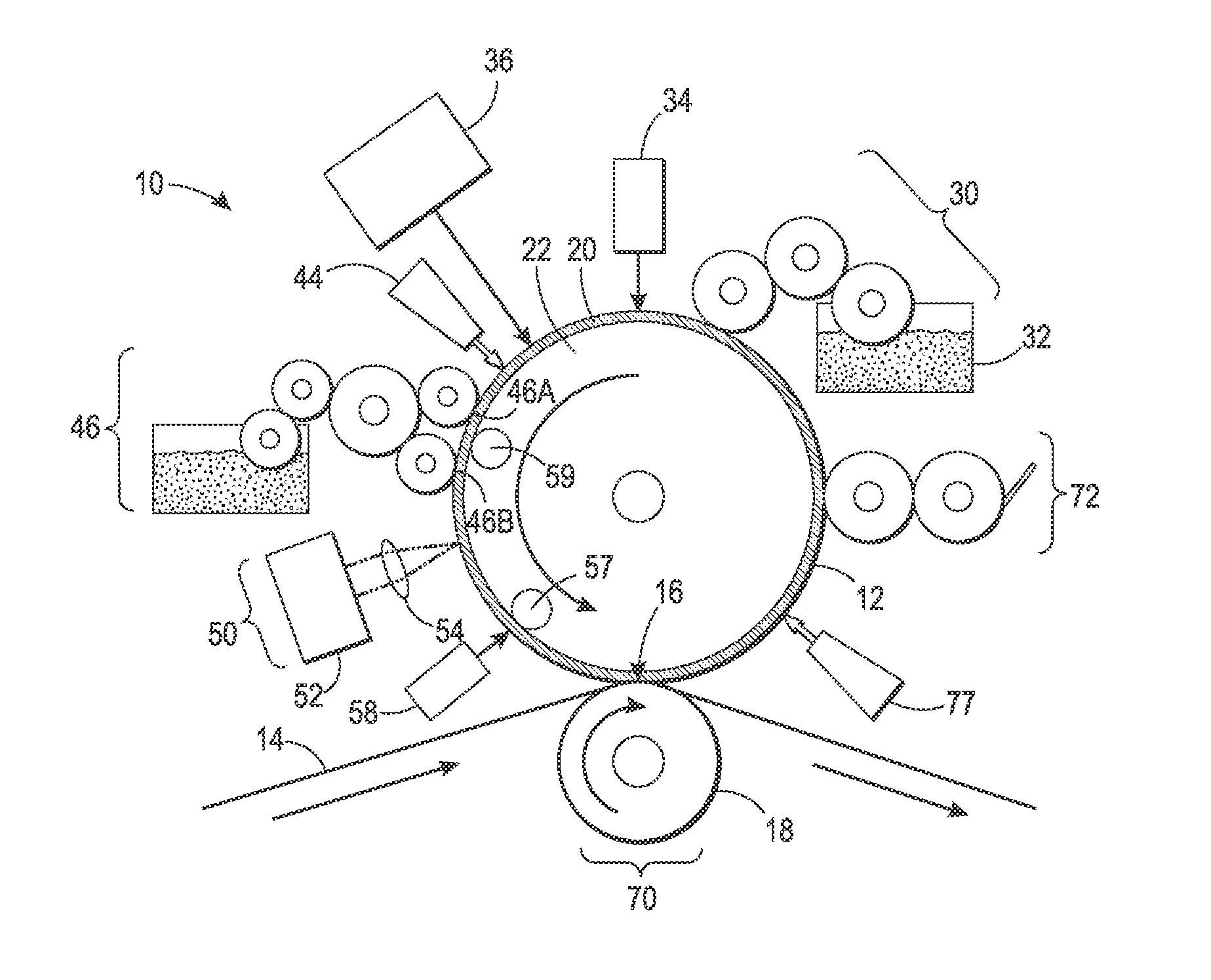
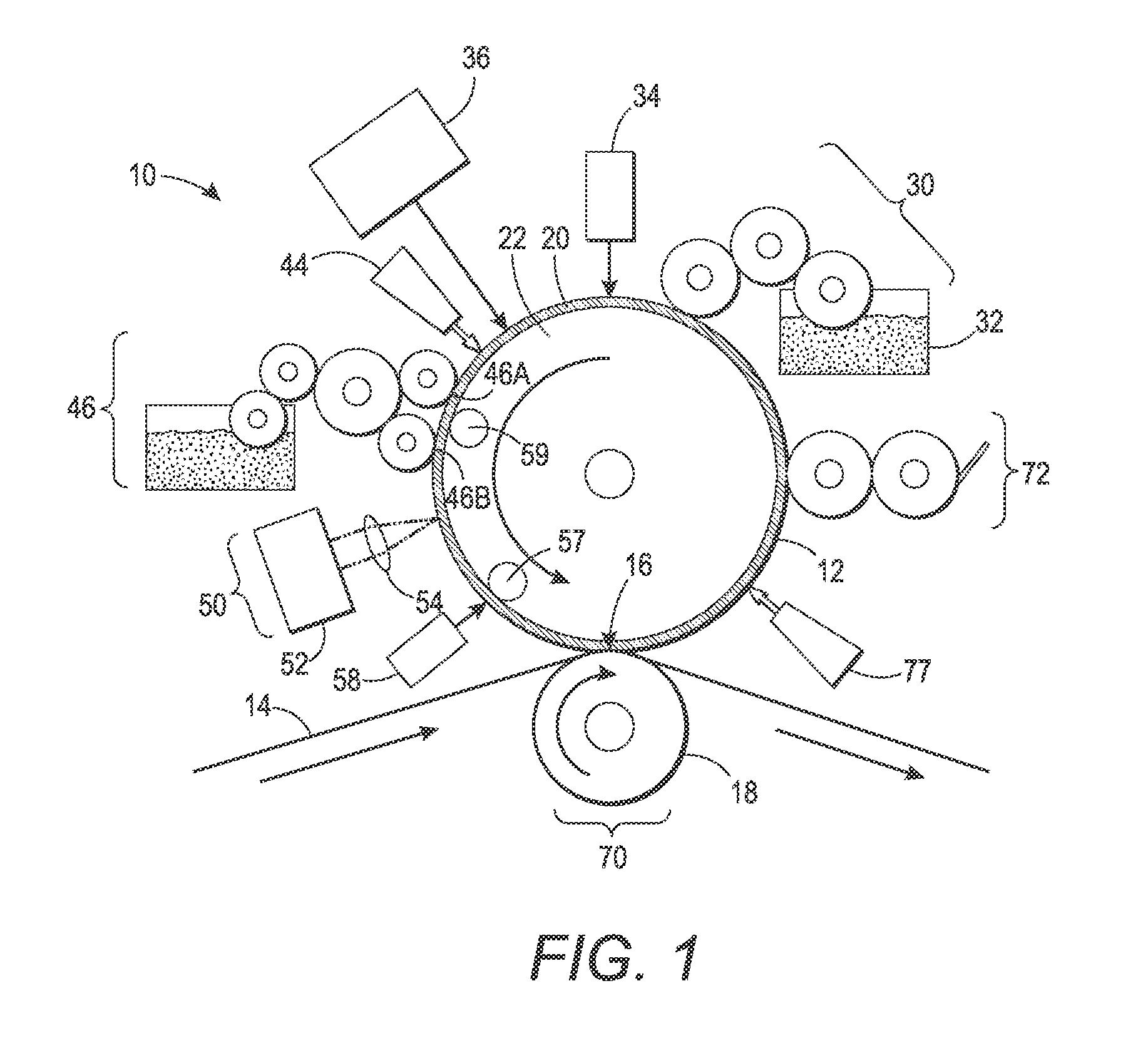
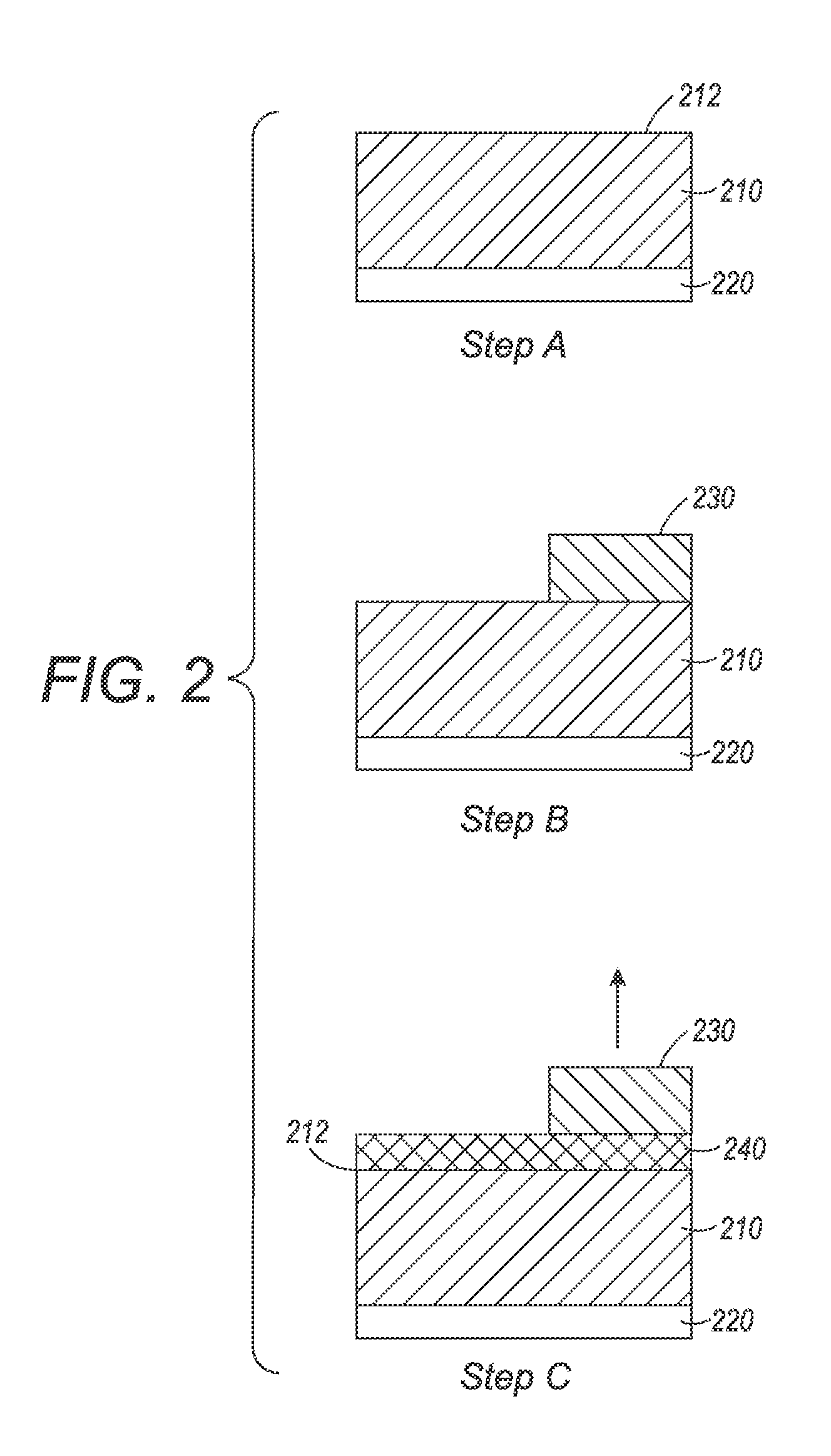
This patent is about a process of printing using ink and a special imaging member. The ink is applied to the surface of the imaging member, which has a layer made of a special elastomer that can swell and release oil. The ink image is transferred to a receiving substrate by applying pressure, which results in a layer of oil between the imaging member and the image, making the transfer more efficient. This technology makes it possible to create high-quality images quickly and easily.

Problems solved by technology

However, they do not permit creating and printing a new pattern from one page to the next without removing and replacing the print cylinder and / or the imaging plate (i.e., the technique cannot accommodate true high speed variable data printing wherein the image changes from impression to impression, for example, as in the case of digital printing systems).
Furthermore, the cost of the permanently patterned imaging plates or cylinders is amortized over the number of copies.

Method used


Image

  • Printing plates doped with release oil
  • Printing plates doped with release oil
  • Printing plates doped with release oil

Examples


example 1

[0096]A series of fluorosilicone samples containing various release oils were prepared as shown in following Table 1. The general procedure for their preparation is described below as for the preparation of sample 1. A carbon dispersion was first prepared by adding Cabot Vulcan XC72 carbon black (5 g), trifluorotoluene (100 g), and stainless steel balls (50 g) into a 250 ml polypropylene bottle. The resulting mixture was shaken at high speed overnight using a Burrell Wrist-Action® shaker. NuSil FS-3502-1A (4.5 g), Halo Carbon 27 (0.6 g), trifluorotoluene (6.0 g), and platinum catalyst (80 microliter, Gelest SIP6831.2 having pt concentration of 2.1-2.4%) was added to a 60 ml polypropylene bottle. The mixture was shaken for at least 30 min before adding the carbon black dispersion (12.0 g), and the resulting mixture was shaken for another 10 min. Nusil hydrofluorosilicone XL150 (0.5 g) was added, all at once, and the resulting mixture was shaken for 10 min and then poured into two pol...

example 2

[0098]This example describes the preparation of a fluorosilicone samples containing D3F as the release oil. A carbon dispersion was first prepared by adding Cabot Vulcan XC72 carbon black (5 g), trifluorotoluene (75 g), and stainless steel balls (50 g) into a 125 ml polypropylene bottle. The resulting mixture was shaken at high speed overnight using a Burrell Wrist-Action® shaker. NuSil FS-3502-1A (4.5 g), D3F (0.75 g), and platinum catalyst (70 microliter, Gelest SIP6831.2 having pt concentration of 2.1-2.4%) was added into a 60 ml polypropylene bottle. The mixture was shaken for 30 min before adding the carbon black dispersion (14.0 g), and the resulting mixture was shaken for another 10 min. A solution of Nusil hydrofluorosilicone XL150 (1.0 g) and trifluorotoluene (4.0 g) was added, all at once, and the resulting mixture was shaken for 10 min and then poured into two polypropylene dishes, each having a diameter of about 2 inches. The mixture was allowed to cure at room temperatu...


PUM

PropertyMeasurementUnit
Percent by massaaaaaaaaaa
Viscosityaaaaaaaaaa
Viscosityaaaaaaaaaa

Abstract

An imaging member surface contains a swellable elastomer doped with a release oil. This aids in complete transfer of ink to a receiving substrate when a thin film of release oil forms upon the surface during application of pressure at the nip.

Description

[0001]The disclosure is related to U.S. patent application Ser. No. 13 / 095,714, filed on Apr. 27, 2011, titled “Variable Data Lithography System,” the disclosure of which is incorporated herein by reference in its entirety. The disclosure is related to co-pending U.S. patent application Ser. No. (Attorney Docket No. 056-0513), filed on the same day as the present disclosure, titled “Imaging Member for Offset Printing Applications,” the disclosure of which is incorporated herein by reference in its entirety; co-pending U.S. patent application Ser. No. (Attorney Docket No. 056-0512), filed on the same day as the present disclosure, titled “Imaging Member for Offset Printing Applications,” the disclosure of which is incorporated herein by reference in its entirety; co-pending U.S. patent application Ser. No. (Attorney Docket No. 056-0511), filed on the same day as the present disclosure, titled “Imaging Member for Offset Printing Applications,” the disclosure of which is incorporated h...

Claims


Application Information

Patent Timeline
IPC IPC(8): B41F1/18C08K5/549C08K5/5419B28B1/14C08L85/00
CPCB41M1/06B41N3/08B41N10/00B41N10/04B41P2227/70C08K5/549B41M5/502
Inventor HSIEH, BINGSTOWE, TIMOTHY D.BADESHA, SANTOKH S.LIU, CHU-HENGKANUNGO, MANDAKINIALVAREZ, JORGE A.HOWE, PATRICK J.KELLY, MATTHEW M.GERVASI, DAVID J.RAMESH, PALGHAT SRINIVAS
Owner XEROX CORP
Why Eureka
Try Eureka