
Canister arrangement structure of straddle type vehicle

a canister arrangement and vehicle technology, applied in the direction of jet propulsion mounting, combustion air/fuel air treatment, cycle equipment, etc., to achieve the effect of effectively supplying evaporated fuel to the engine and reducing the length of the purge pip

Inactive Publication Date: 2014-03-06
HONDA MOTOR CO LTD
View PDF11 Cites 26 Cited by
  • Summary
  • Abstract
  • Description
  • Claims
  • Application Information

AI Technical Summary

Benefits of technology

The purpose of this invention is to make the purge pipe (a tool used to supply evaporated fuel to an engine) as short as possible, to effectively deliver it to the engine. The technical effect of this is a reduction in the length of the purge pipe.

Problems solved by technology

However, the purge pipe is required to be as short as possible for the purpose of effectively supplying evaporated fuel, making the pipe structure compact and reducing the weight thereof.

Method used


Image

  • Canister arrangement structure of straddle type vehicle
  • Canister arrangement structure of straddle type vehicle
  • Canister arrangement structure of straddle type vehicle

Examples


Embodiment Construction

[0032]Hereinafter, an embodiment of the present invention will be described with reference to the drawings. In the drawings, directions of front and rear, upper and lower, and right and left are based on the vehicle.

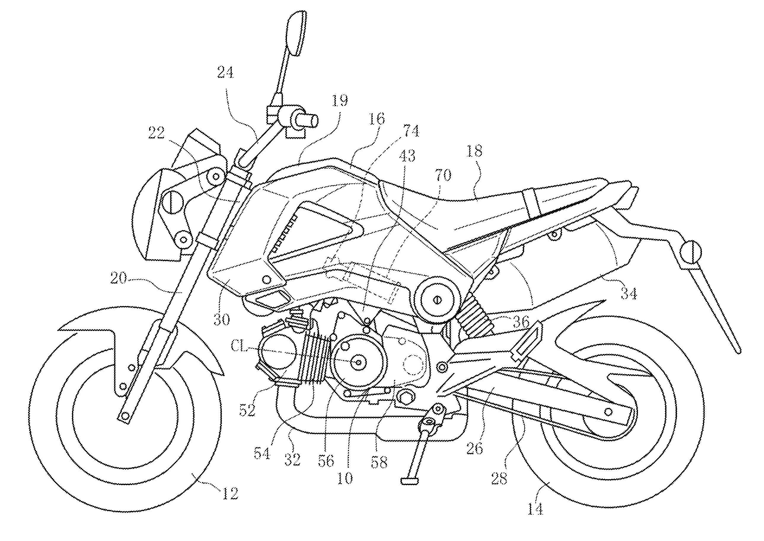
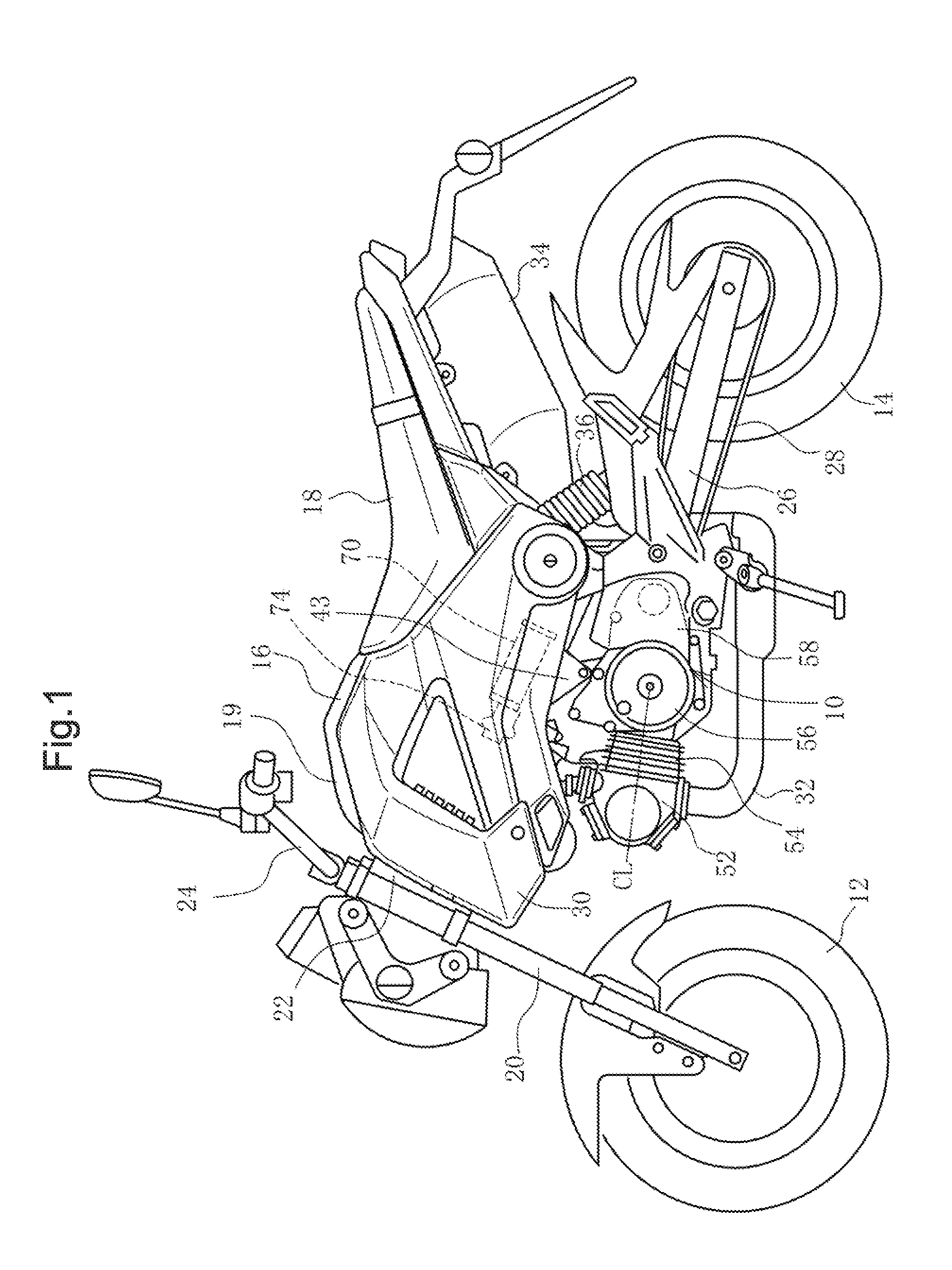
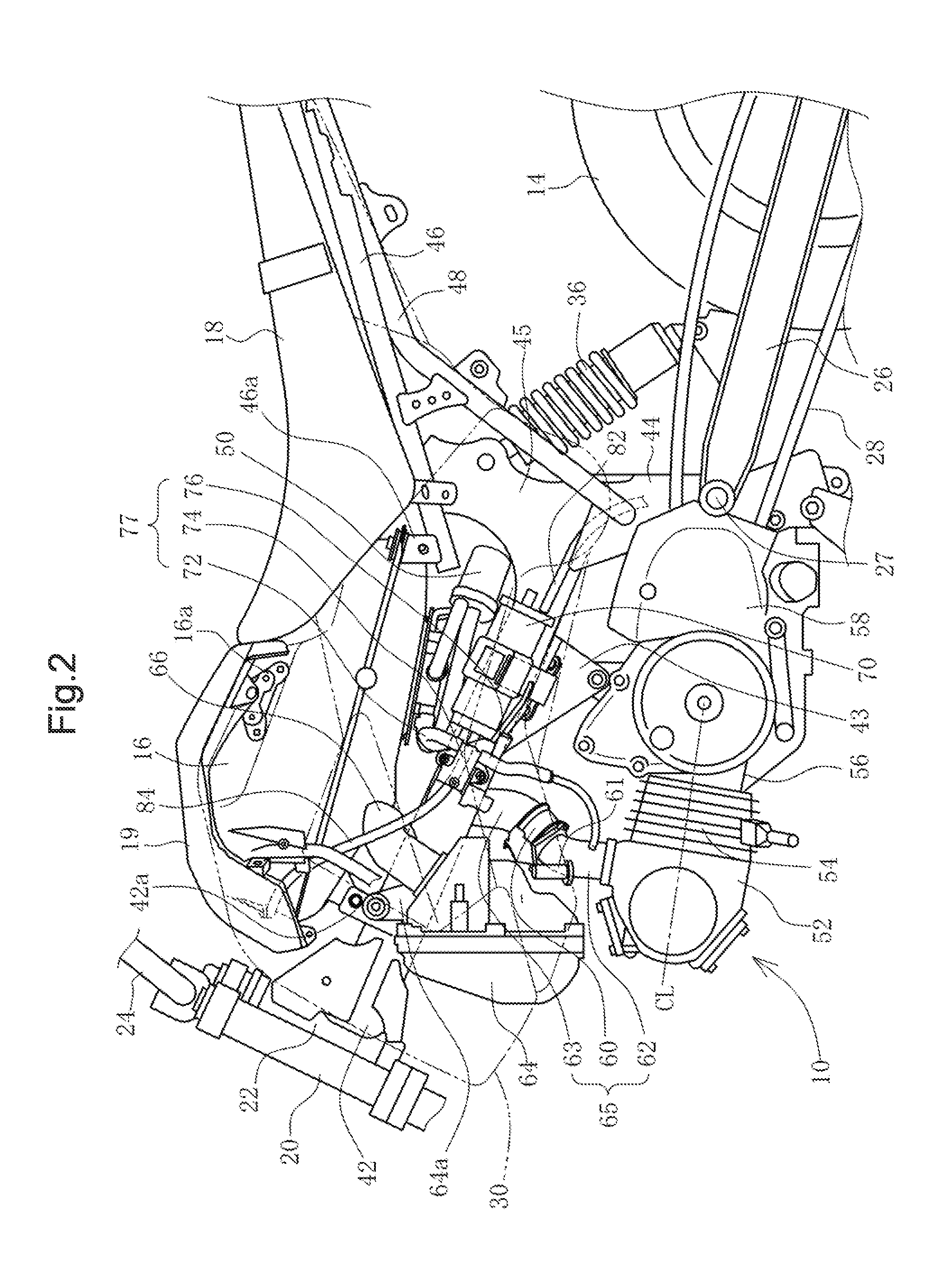
[0033]FIG. 1 is a left side view of a motorcycle of a straddle type vehicle. FIG. 2 is a drawing showing the inside of a body cover with reference to the front portion of the vehicle body of FIG. 1. FIG. 3 is a perspective view of a body frame.

[0034]In FIG. 1, an engine 10 is disposed in the center of the vehicle body with a front wheel 12 and a rear wheel 14 being disposed in the front and in the rear thereof, respectively. A fuel tank 16 is disposed above the engine 10. A seat 18 is disposed in the rear portion thereof.

[0035]The front wheel 12 is supported on the lower end of a front fork 20. The front fork 20 is rotatably supported on a head pipe 22, which is provided on the front end of a body frame (which will be described later), and is steered by a handle 24.

[0036...


PUM


Abstract

An engine supported on a main frame with an air cleaner disposed above a cylinder head. Air is supplied from an upper direction via an intake passage. A canister is supported above a crankcase and on the side surface of the main frame. A purge pipe connects between a front end portion of the canister and the intake passage. The purge pipe has a short length and includes a purge control valve in an intermediate portion and includes a first purge pipe for connecting the purge control valve with the canister, and a second purge pipe for connecting the purge control valve with the intake passage. Evaporated fuel from a fuel tank is supplied to the canister via a discharge pipe. A drain tube is connected at the rear end of the canister and at the lower position relative to the connecting portion of the first purge pipe.

Description

CROSS-REFERENCE TO RELATED APPLICATIONS[0001]The present application claims priority under 35 USC 119 to Japanese Patent Application No. 2012-195537 filed Sep. 5, 2012 the entire contents of which are hereby incorporated by reference.BACKGROUND OF THE INVENTION[0002]1. Field of the Invention[0003]The present invention relates to a canister arrangement structure of a straddle type vehicle wherein the length of a purge pipe is shortened.[0004]2. Description of Background Art[0005]It is well known that in a motorcycle of a straddle type vehicle, a canister is disposed to trap evaporated fuel in a fuel tank and to supply the evaporated fuel to an engine for combustion. A horizontal cylinder of the engine extends in the front-and-rear direction and is disposed in the center of the vehicle body with an intake passage being disposed above the horizontal cylinder. The canister is disposed sideways behind the engine such that the longitudinal direction thereof corresponds to the width direct...

Claims


Application Information

Patent Timeline
IPC IPC(8): F02M25/08B62K11/00
CPCB62K11/00F02M25/0854B62J37/00B62K11/04F02M35/162F02M25/089F02M35/024
Inventor KONO, SHO
Owner HONDA MOTOR CO LTD
Learn More