

Constraining clock skew in a resonant clocked system
a resonant clock and clock skew technology, applied in the field of resonant clock networks, can solve problems such as a significant portion of the overall power consumption
- Summary
- Abstract
- Description
- Claims
- Application Information
AI Technical Summary
Benefits of technology
Problems solved by technology
Method used
Image

Examples
Embodiment Construction
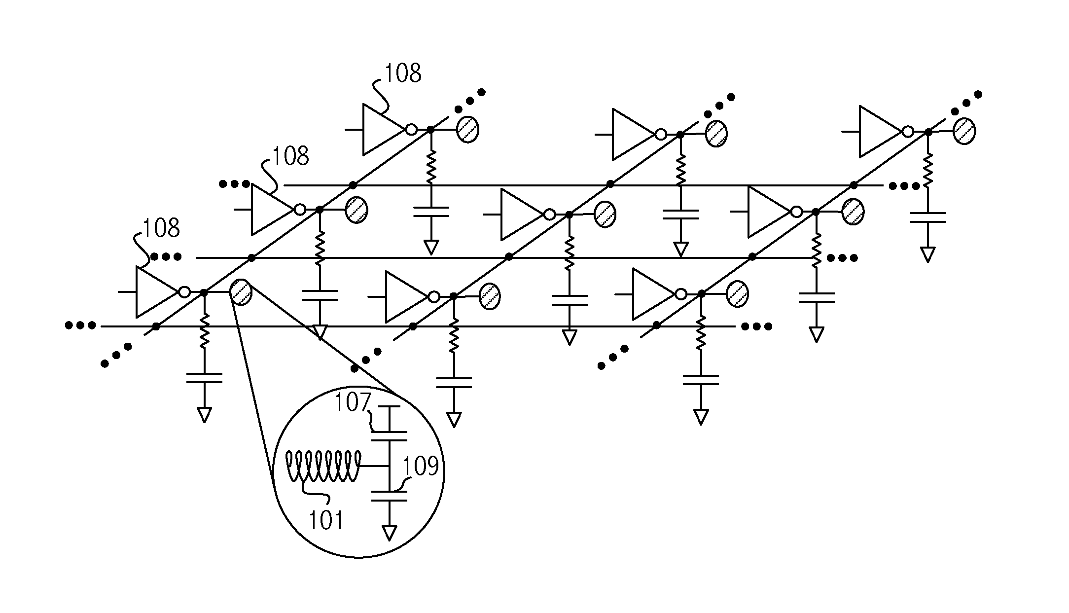
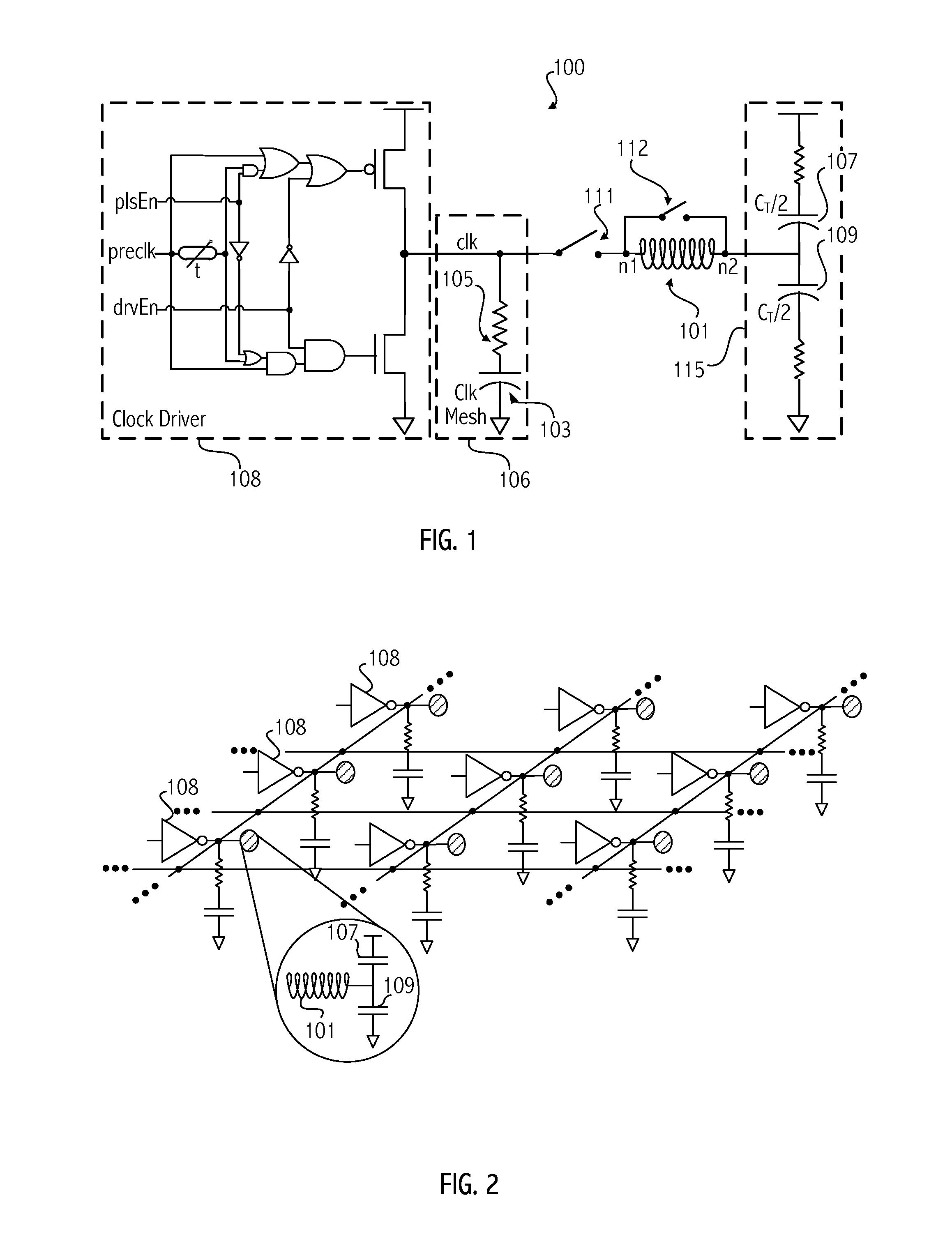
[0005]Accordingly, in one embodiment an integrated circuit includes a first resonant clock domain of a resonant clock network coupled to a second resonant clock domain of the resonant clock network by a clock mesh branch. A clock driver is associated with the first resonant clock domain. An inductor connects to the clock mesh branch at a boundary between the first resonant clock domain and the second resonant clock domain.
[0006]In some embodiments a method includes supplying a first portion of a clock signal to circuits of a first resonant clock domain of a resonant clock network and circuits of a second resonant clock domain of the resonant clock network from an inductor connected at a boundary between the first resonant clock domain and the second resonant clock domain.
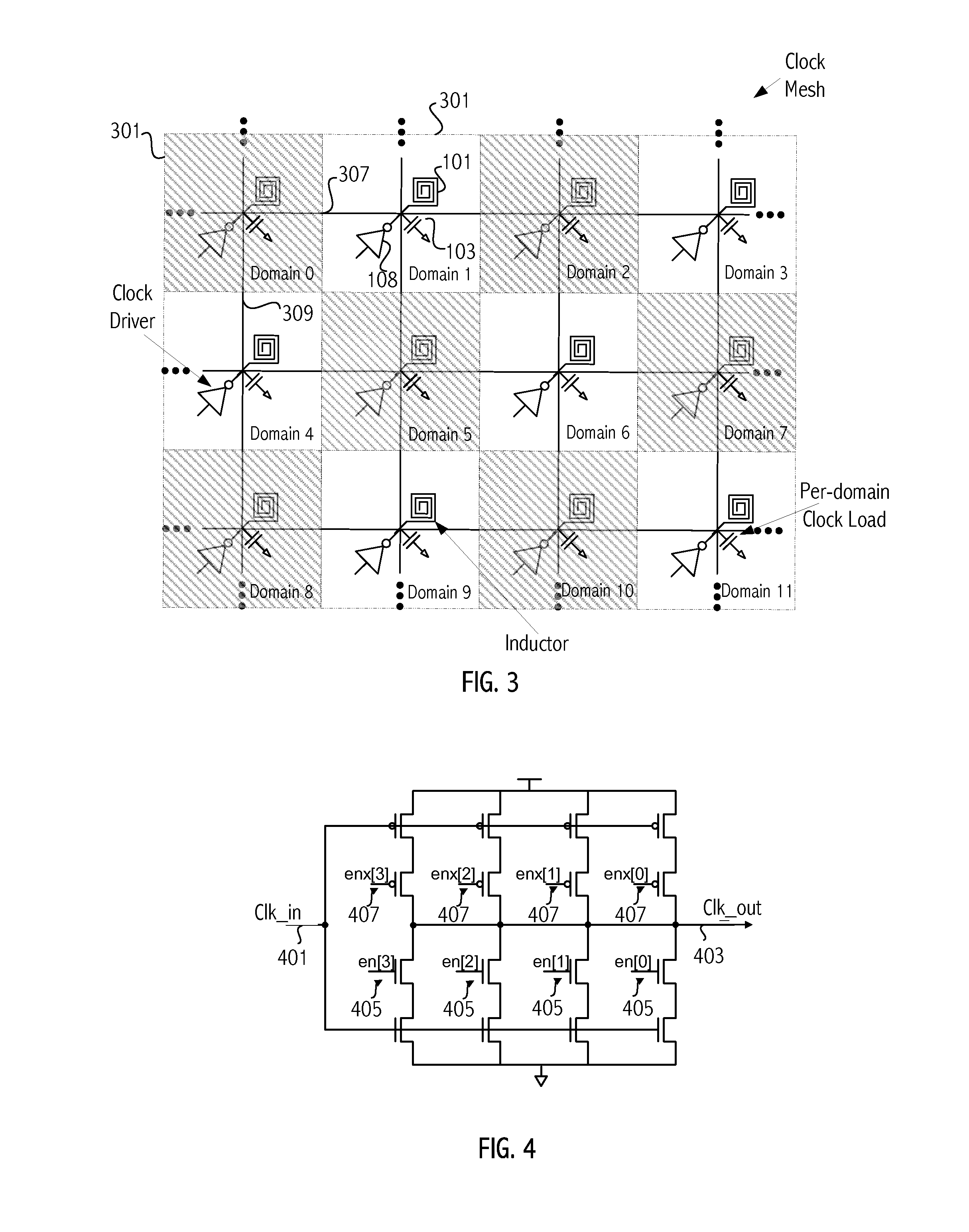
[0007]In some embodiments an integrated circuit includes a plurality of resonant clock domains of a resonant clock network. Respective clock drivers are associated with respective ones of the resonant clock domains,...
PUM
 Abstract
Description
Claims
Application Information