
Liquid jetting apparatus, piezoelectric actuator, and method for producing the liquid jetting apparatus

Active Publication Date: 2014-03-06
BROTHER KOGYO KK
View PDF3 Cites 21 Cited by
  • Summary
  • Abstract
  • Description
  • Claims
  • Application Information

AI Technical Summary

Benefits of technology

The present invention simplifies the connection structure between the piezoelectric element and the wiring substrate, which reduces production costs and simplifies the manufacturing process. This is achieved by eliminating the need for separate electrodes on the piezoelectric element and the wiring substrate, and utilizing the permeation action by the capillary force to fill the plurality of first grooves with the liquid conductive material after forming them in the joint surface of the wiring substrate with the piezoelectric element. This results in a more robust and reliable connection with a high adhesion to the wiring substrate.

Problems solved by technology

Therefore, the connection structure between the wiring substrate and the piezoelectric layer (piezoelectric element) is complicated.
This accordingly increases the number of production processes, thereby suffering disadvantage in terms of cost.

Method used


Image

  • Liquid jetting apparatus, piezoelectric actuator, and method for producing the liquid jetting apparatus
  • Liquid jetting apparatus, piezoelectric actuator, and method for producing the liquid jetting apparatus
  • Liquid jetting apparatus, piezoelectric actuator, and method for producing the liquid jetting apparatus

Examples


first embodiment

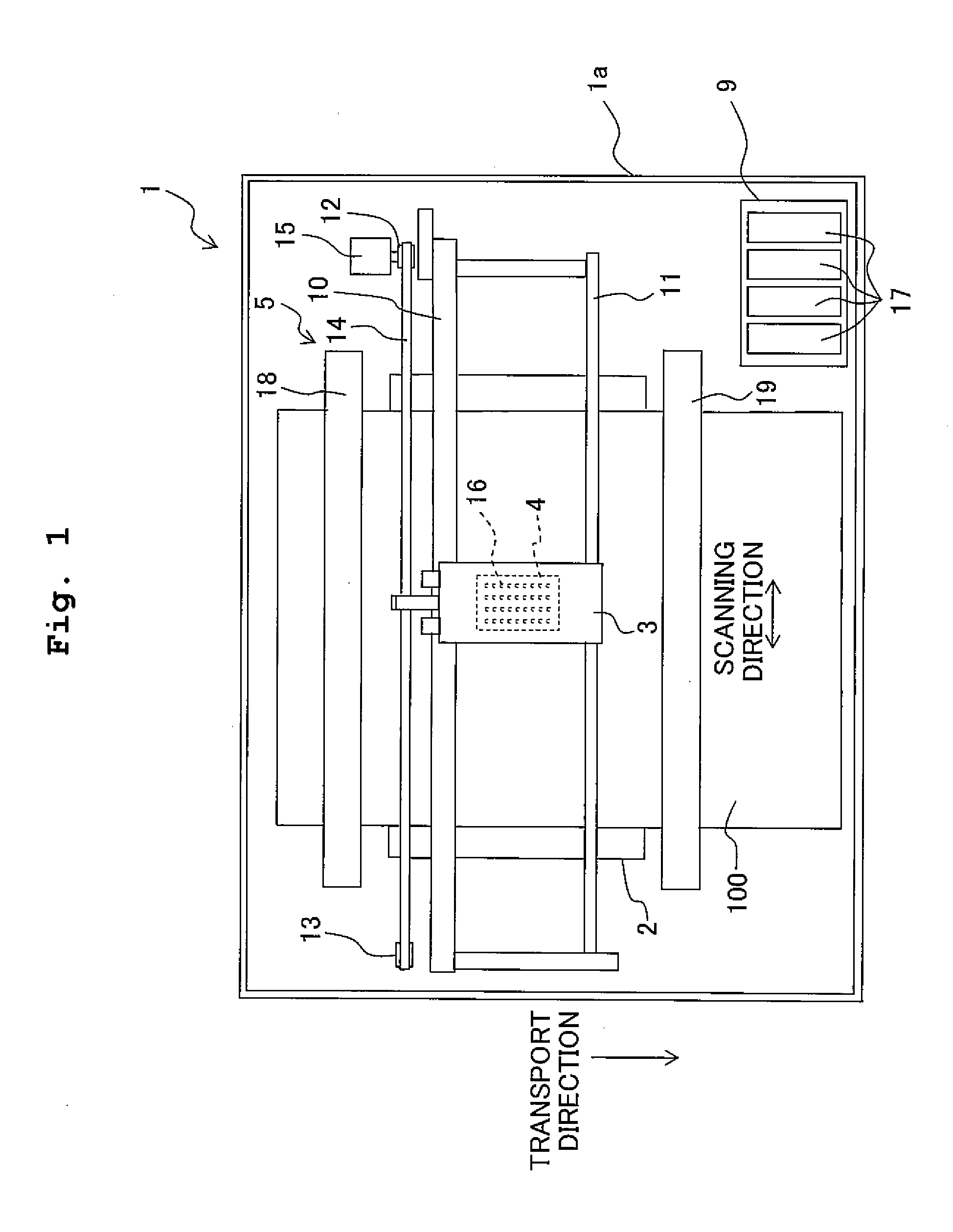
[0033]Next, the present invention will be explained. First, referring to FIG. 1, a schematic construction of an ink jet printer 1 will be explained. Further, in the following explanations, the front side of the page of FIG. 1 is defined to be the upper side while the back side of the page is defined to be the lower side, and the directional terms “upper” and “lower” are used as appropriate. As shown in FIG. 1, the ink jet printer 1 includes a platen 2, a carriage 3, an inkjet head 4, a transport mechanism 5, etc.

[0034]A sheet of recording paper 100, which is a recording medium, is placed on the upper surface of the platen 2. Further, above the platen 2, two guide rails 10 and 11 are provided to extend parallel to a left-right direction (a scanning direction) of FIG. 1. The carriage 3 is configured to be movable reciprocatingly in the scanning direction along the two guide rails 10 and 11 in an area facing the platen 2. Further, the carriage 3 is connected to an endless belt 14 wound...

second embodiment

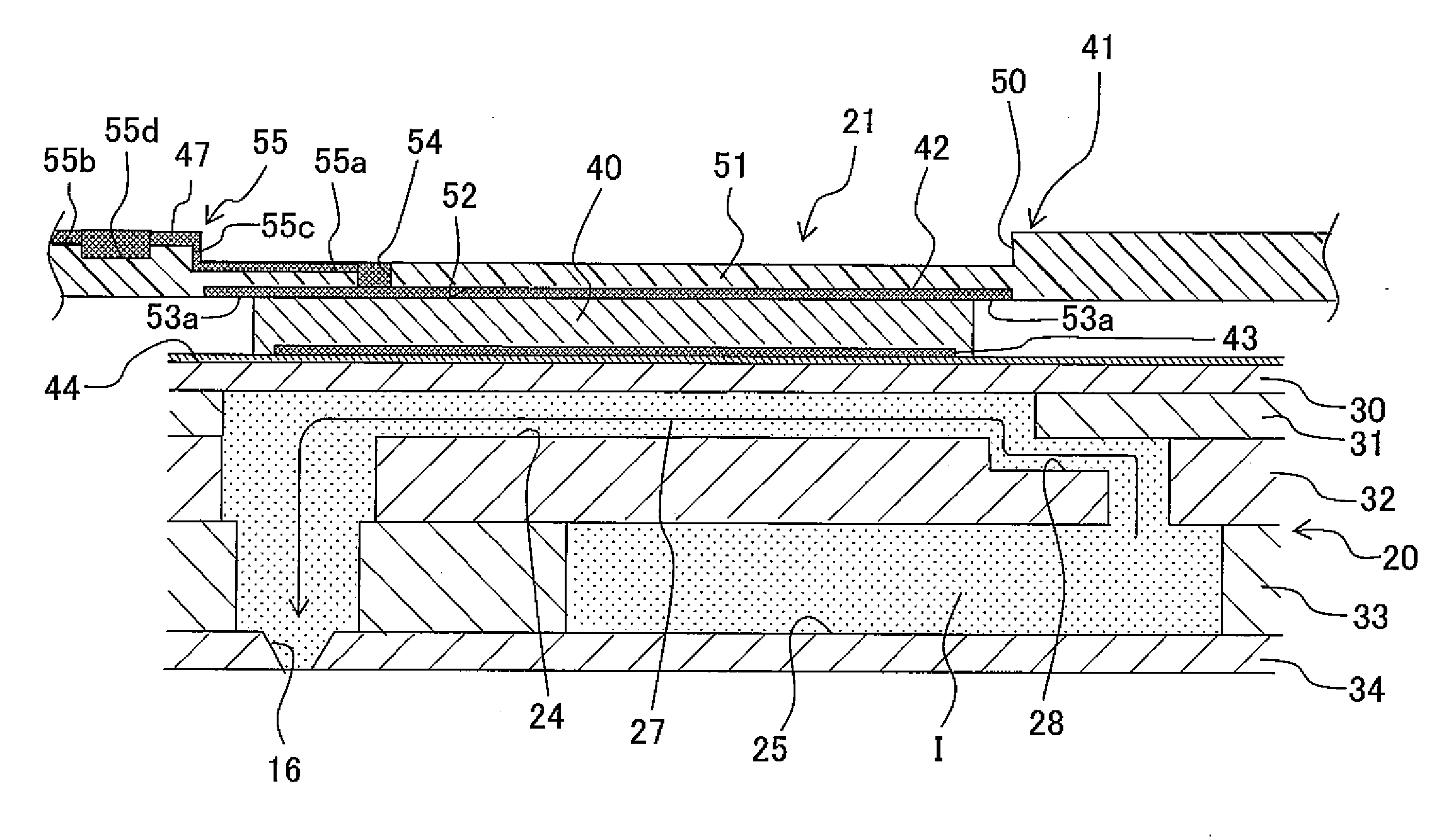
[0072]Further, the atmosphere communication groove 56, and is connected to an atmosphere communication hole 57 penetrating through the wiring substrate 41 in the thickness direction to open to both upper and lower surfaces. By virtue of this, even if the wiring substrate 41 contacts with the upper surface of the piezoelectric layer 140 and the plurality of filling grooves 52 are closed up by the piezoelectric layer 140, the plurality of filling grooves 52 still communicate with the atmosphere via the atmosphere communication groove 56 and atmosphere communication hole 57. That is, in the second embodiment, an atmosphere communication passage 58, through which the plurality of filling grooves 52 communicate with the atmosphere, is constituted by the atmosphere communication groove 56 and atmosphere communication hole 57.

[0073]If a liquid conductive ink (conductive material) is supplied to each of the supply grooves 155 in a state that the piezoelectric layer 140 is in contact with th...


PUM

PropertyMeasurementUnit
Thicknessaaaaaaaaaa
Electrical conductivityaaaaaaaaaa
Lengthaaaaaaaaaa

Abstract

A liquid jetting apparatus includes a channel unit in which a liquid channel including a nozzle for jetting a liquid is formed, and a piezoelectric actuator provided on the channel unit and configured to apply jetting energy to the liquid inside the liquid channel. The piezoelectric actuator has a piezoelectric element and a wiring substrate in which a first electrode and a wire electrically connected to the first electrode are formed and which is joined to one surface of the piezoelectric element. The first electrode is configured to make contact with the piezoelectric element.

Description

CROSS REFERENCE TO RELATED APPLICATION[0001]The present application claims priority from Japanese Patent Application No. 2012-191112, filed on Aug. 31, 2012 and Japanese Patent Application No. 2012-191114, filed on Aug. 31, 2012, the disclosure of which are incorporated herein by reference in its entirety.BACKGROUND OF THE INVENTION[0002]1. Field of the Invention[0003]The present invention relates to a liquid jetting apparatus, a piezoelectric actuator, and a method for producing the liquid jetting apparatus.[0004]2. Description of the Related Art[0005]Conventionally, as a configuration of piezoelectric actuators used for various purposes, there has been known such configuration in which a wiring substrate is connected to a surface electrode of a piezoelectric element to supply a signal for driving the piezoelectric element.[0006]Conventionally, there have been known piezoelectric actuators provided for an ink-jet head to jet liquid droplets. Such ink-jet head is provided with a cha...

Claims


Application Information

Patent Timeline
IPC IPC(8): B41J2/14B41J2/16H01L41/047
CPCB41J2/14201B41J2/1621H01L41/047B41J2/14233B41J2002/14459B41J2002/14491B41J2202/18Y10T29/42H10N30/875H10N30/2047H10N30/87
Inventor KONDO, HIROFUMI
Owner BROTHER KOGYO KK
Features
  • Generate Ideas
  • Intellectual Property
  • Life Sciences
  • Materials
  • Tech Scout
  • Unparalleled Data Quality
  • Higher Quality Content
  • 60% Fewer Hallucinations
Learn More