Hydrogen generation assemblies

Inactive Publication Date: 2014-03-06
ELEMENT 1
View PDF12 Cites 20 Cited by
  • Summary
  • Abstract
  • Description
  • Claims
  • Application Information

AI Technical Summary

Benefits of technology

[0007]In some embodiments, the hydrogen generation assembly may include a fuel processing assembly configured to receive a feed stream and to be operable among a plurality of modes, including a run mode in which the fuel processing assembly produces a product hydrogen stream from the feed stream, and a standby mode in which the fuel processing assembly does not produce the product hydrogen stream from the feed stream. The hydrogen generation assembly may additionally include a buffer tank configured to contain the product hydrogen stream, and a product conduit fluidly connecting the fuel processing assembly and the buffer tank. The hydrogen generation assembly may further include a tank sensor assembly configured to detect pressure in the buffer tank, and a control assembly configured to operate the fuel processing assembly between the run and standby modes based, at least in part, on the detected pressure in the buffer tank.
[0008]Some embodiments may provide a steam reforming hydrogen generation assembly configured to receive at least one feed stream and generate a reformate stream containing hydrogen gas as a majority component and other gases. In some embodiments, the steam reforming hydrogen generation assembly may include an enclosure having an exhaust port, and a hydrogen-producing region contained within the enclosure and configured to produce, via a steam refor

Problems solved by technology

The generated or produced hydrogen

Method used


Image

  • Hydrogen generation assemblies
  • Hydrogen generation assemblies
  • Hydrogen generation assemblies

Examples


Example

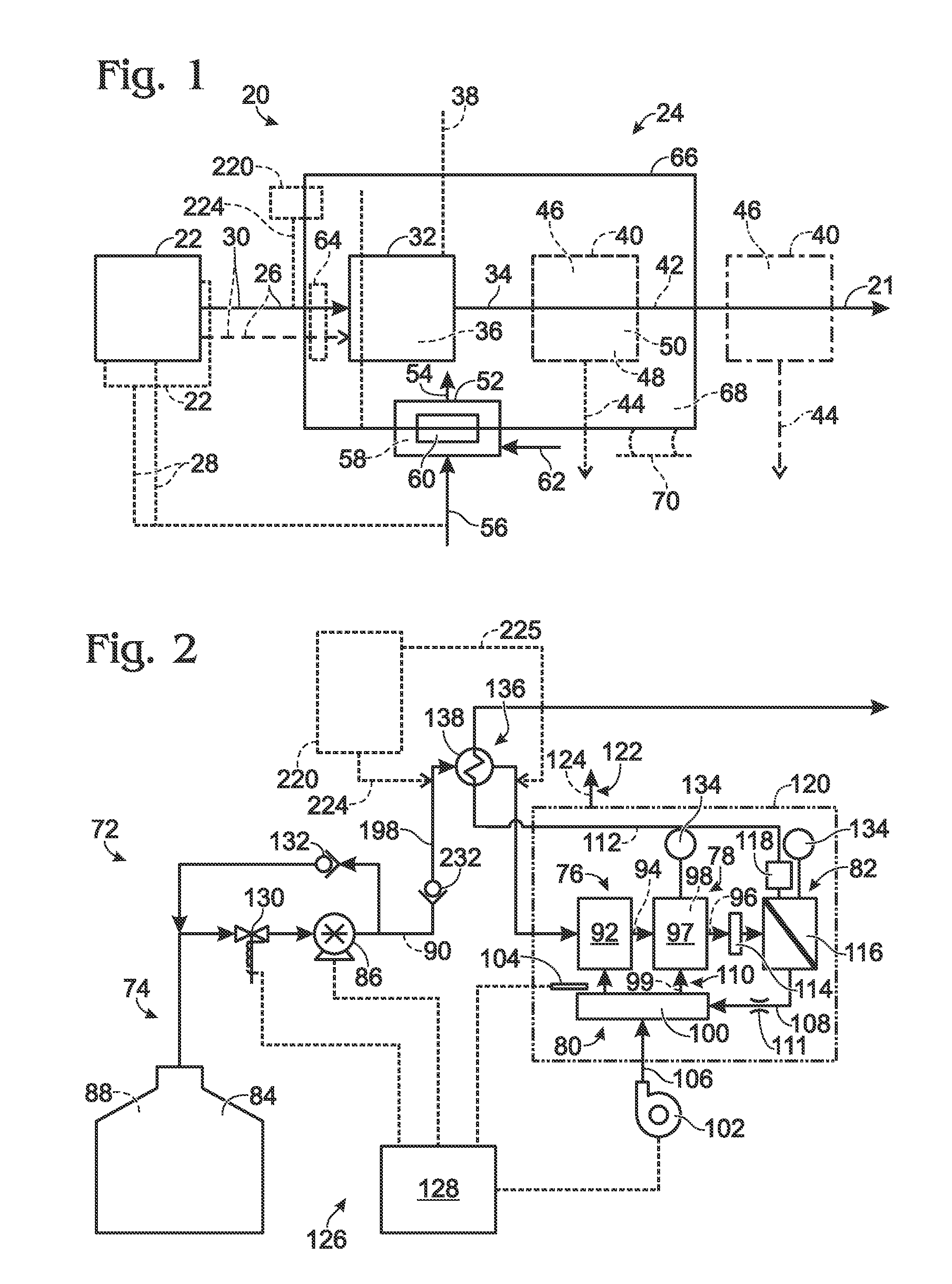
[0026]FIG. 1 shows an example of a hydrogen generation assembly 20. Unless specifically excluded hydrogen generation assembly may include one or more components of other hydrogen generation assemblies described in this disclosure. The hydrogen generation assembly may include any suitable structure configured to generate a product hydrogen stream 21. For example, the hydrogen generation assembly may include a feedstock delivery system 22 and a fuel processing assembly 24. The feedstock delivery system may include any suitable structure configured to selectively deliver at least one feed stream 26 to the fuel processing assembly.

[0027]In some embodiments, feedstock delivery system 22 may additionally include any suitable structure configured to selectively deliver at least one fuel stream 28 to a burner or other heating assembly of fuel processing assembly 24. In some embodiments, feed stream 26 and fuel stream 28 may be the same stream delivered to different parts of the fuel process...


PUM


Abstract

Hydrogen generation assemblies and their components are disclosed. In some embodiments, the assemblies may include a pump controller configured to select a flowrate from a plurality of flowrates based on detected pressure, and to operate the pump at the selected flowrate. In some embodiments, the assemblies may include a purge valve assembly configured to allow at least one pressurized gas to flow through a purge conduit from a pressurized gas assembly to a fuel processing assembly when power to the fuel processing assembly is interrupted. In some embodiments, the assemblies may include a damper controller configured to move a damper between fully open and closed positions based, at least in part, on detected temperature in a hydrogen-producing region. In some embodiments, the assemblies may include a reformer controller configured to operate a fuel processing assembly between run and standby modes based, at least in part, on detected pressure.

Description

BACKGROUND OF THE DISCLOSURE[0001]A hydrogen generation assembly is an assembly that converts one or more feedstocks into a product stream containing hydrogen gas as a majority component. The feedstocks may include a carbon-containing feedstock and, in some embodiments, also may include water. The feedstocks are delivered to a hydrogen-producing region of the hydrogen generation assembly from a feedstock delivery system, typically with the feedstocks being delivered under pressure and at elevated temperatures. The hydrogen-producing region is often associated with a temperature modulating assembly, such as a heating assembly or cooling assembly, which consumes one or more fuel streams to maintain the hydrogen-producing region within a suitable temperature range for effectively producing hydrogen gas. The hydrogen generation assembly may generate hydrogen gas via any suitable mechanism(s), such as steam reforming, autothermal reforming, pyrolysis, and / or catalytic partial oxidation.[...

Claims


Application Information

Patent Timeline
IPC IPC(8): B01J19/00G05D16/00G05D23/00
CPCC01B3/50C01B3/505C01B3/56C01B3/501C01B2203/0233C01B2203/0283C01B2203/0405C01B2203/043C01B2203/044C01B2203/0445C01B2203/047C01B2203/0811C01B2203/1217C01B2203/1235C01B2203/169C01B3/32C01B2203/1633C01B2203/1647
Inventor EDLUND, DAVID J.SCHLUTER, ROBERT
Owner ELEMENT 1
Why Eureka
Try Eureka