Structural monitoring

a technology for monitoring structures and structures, applied in the direction of pedestrian/occupant safety arrangements, anti-theft devices, instruments, etc., can solve the problems of subject to wear and tear, and other structures being subject to abuse or malicious damage,

Inactive Publication Date: 2014-03-06
INTELLIGENT TECH INT
View PDF13 Cites 24 Cited by
  • Summary
  • Abstract
  • Description
  • Claims
  • Application Information

AI Technical Summary

Problems solved by technology

Bridges and other infrastructure are used daily and subject to wear and tear.
Other structures can be subject to abuse or malicious damage such as dams, buildings, fences or other border structures, roadways, etc.

Method used


Image

  • Structural monitoring
  • Structural monitoring
  • Structural monitoring

Examples


Embodiment Construction

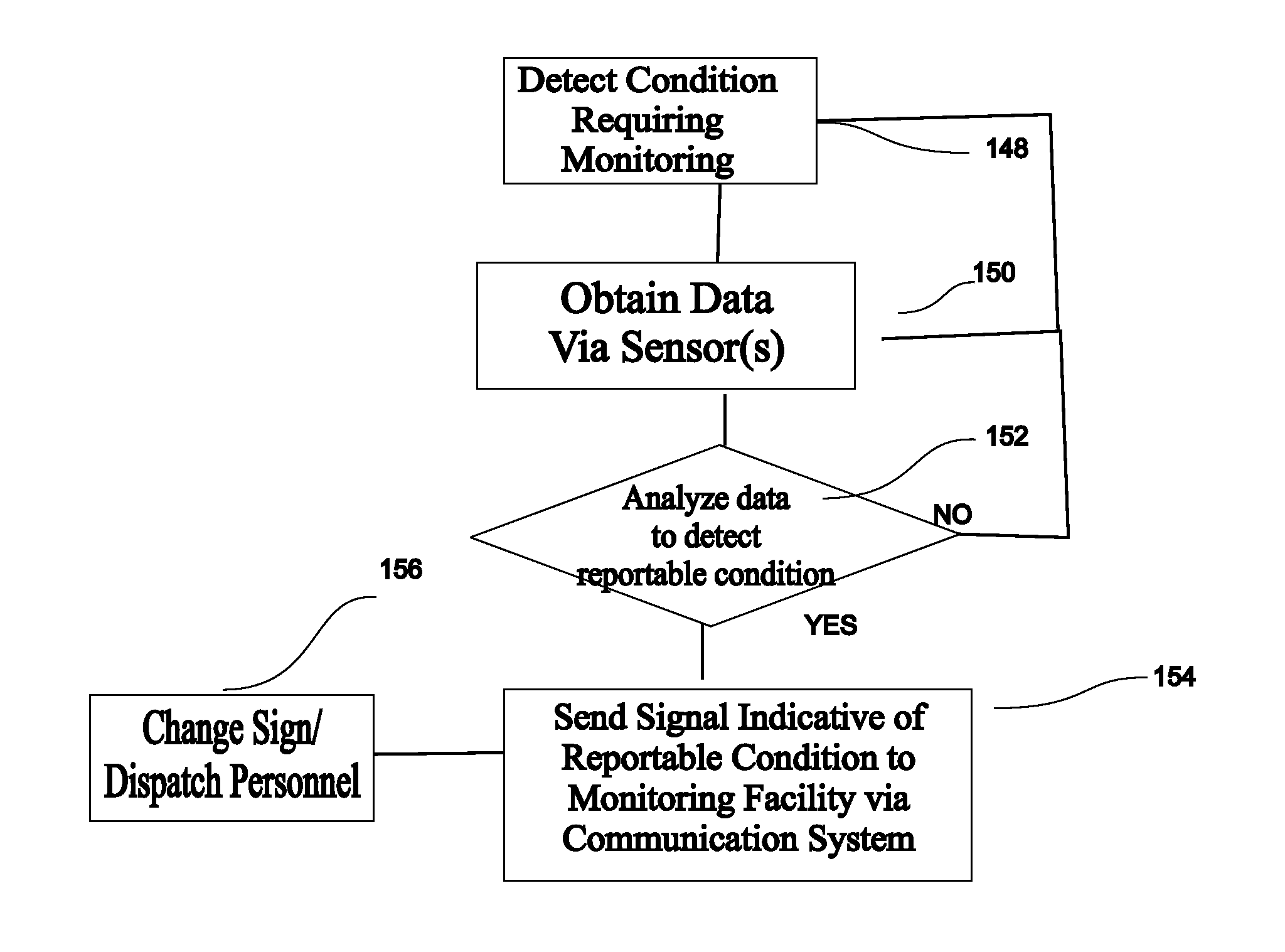
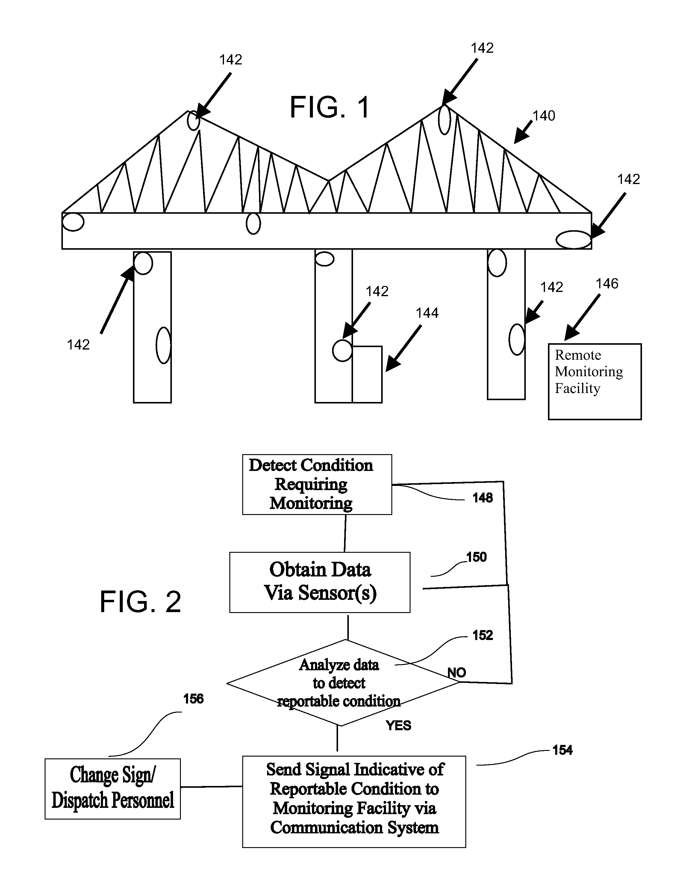
[0026]Periodically, a boat or barge impacts with the structure of a bridge resulting in the collapse of a road, railroad or highway and often multiple fatalities. Additionally such structures are subject to normal deterioration over time eventually resulting in their failure. Usually such an event can be sensed prior to the collapse of the structure by monitoring the accelerations, vibrations, displacement, and / or stresses in or of the structural members. When such an event is sensed, a message can be sent to a satellite, to the cell phone infrastructure or other communication system, and / or forwarded to the Internet, and thus to the authorities and to a warning sign or signal that has been placed at a location preceding entry onto the bridge. Alternately, the sensing device can send a signal directly to the relevant sign either in addition or instead of to a satellite, or other communication system.

[0027]Referring in this regard to FIGS. 1 and 2, a bridge which can be monitored in ...


PUM


Abstract

System for monitoring a structure includes at least one monitoring arrangement attached at a respective location to the structure, each monitoring arrangement having at least one inertial measurement unit (IMU) that measures acceleration and / or angular motion in any direction and rotation about any axis, a Global Navigation Satellite System (GNSS) receiver that determines its location, and a wireless communication system that transmits information derived from acceleration and / or angular motion measured by the IMU and a location determination by the GNSS receiver. Further, each monitoring arrangement may include a microphone, chemical sensor, a visual or IR light sensor, a radiation sensor, a magnetic sensor, and / or a strain sensor. As an alternative, the monitoring arrangements may include only IMUs or only GNSS receivers.

Description

CROSS REFERENCE TO RELATED APPLICATIONS[0001]This application is a continuation-in-part of U.S. patent application Ser. No. 11 / 935,819 filed Nov. 6, 2007, which is:[0002]1. a continuation-in-part (CIP) of U.S. patent application Ser. No. 10 / 940,881 filed Sep. 13, 2004, now U.S. Pat. No. 7,663,502, which is:[0003]A. a CIP of U.S. patent application Ser. No. 10 / 457,238 filed Jun. 9, 2003, now U.S. Pat. No. 6,919,803 which claims priority under 35 U.S.C. §119(e) of U.S. provisional patent application Ser. No. 60 / 387,792 filed Jun. 11, 2002, now expired;[0004]B. a CIP of U.S. patent application Ser. No. 10 / 931,288 filed Aug. 31, 2004, now U.S. Pat. No. 7,164,117;[0005]2. a CIP of U.S. patent application Ser. No. 11 / 278,979 filed Apr. 7, 2006, now U.S. Pat. No. 7,386,372, which is a CIP of U.S. patent application Ser. No. 10 / 931,288 filed Aug. 31, 2004, now U.S. Pat. No. 7,164,117;[0006]3. a CIP of U.S. patent application Ser. No. 11 / 380,574 filed Apr. 27, 2006, now U.S. Pat. No. 8,159,3...

Claims


Application Information

Patent Timeline
Patent Type & Authority Applications(United States)
IPC IPC(8): G01M99/00
CPCG01M99/004E05Y2900/542B60R25/25B60R16/037B60R21/013B60R21/0132B60R21/0134B60R21/0136G01M5/0008G01S17/88G01S7/417G01S7/4802G01S7/539G01S13/04G01S15/04G01S15/06G01S15/42G01S15/87G01S15/88H01Q1/3291B60R2001/1223B60R2001/1253B60R2021/01315E05Y2900/55E05Y2900/516G01M5/0033B60R21/01554B60R21/01548B60R21/01546B60R21/01536B60R21/01532B60R21/01516B60R21/01534B60R21/01538B60R21/01542B60R21/01552B60R21/0152B60R21/0153B60R21/01544E05F15/43E05F15/431E05F2015/433G01S17/04
Inventor BREED, DAVID S.
Owner INTELLIGENT TECH INT
Why Eureka
Try Eureka