

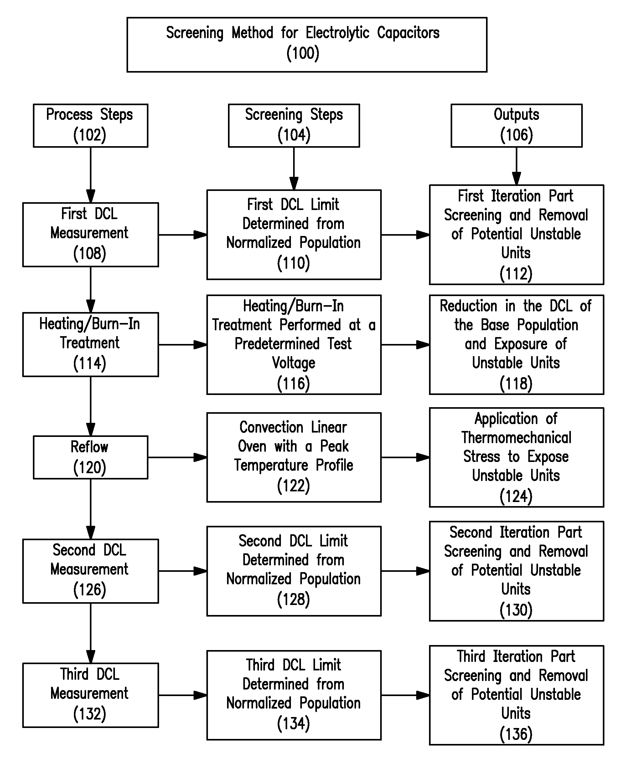
Screening Method for Electrolytic Capacitors
a technology of electrolytic capacitors and electrolytic capacitors, which is applied in capacitor manufacturing, semiconductor/solid-state device testing/measurement, instruments, etc., can solve the problems of long-term instability, inability to detect latent defects, and unstable parts passing through to the normal population
- Summary
- Abstract
- Description
- Claims
- Application Information
AI Technical Summary
Benefits of technology
Problems solved by technology
Method used
Image

Examples
example 1
125° C. 2 / 3 Rated Voltage Life Testing
[0092]Referring to FIGS. 6-9, 100 capacitors per lot from 10 lots falling into “Zone 1” in FIG. 5 above were burned-in at 125° C. for a period of 42 hours at 1.0 times the rated voltage of the capacitors. The parts were then mounted on FR-4 boards and subjected to a 1000 hour life test at 125° C. and 2 / 3 rated voltage. The leakage current (DCL) was then determined at a temperature of 25° C. and at the rated voltage for the parts after completion of the 1000 hour test.
[0093]As seen in FIG. 6, the “Zone 1” capacitors of FIG. 5 overall exhibited a slightly higher leakage current in FIG. 6 post-mounting compared to FIG. 5, which, as discussed above, represents the first leakage current determination. However, the capacitors have a leakage current that is still below the predetermined 0.225 μA hard cut / failure limit for the capacitors. Likewise, as seen in FIG. 7, at the end of the 1000 hour 125° C. life test at 2 / 3 rated voltage, the “Zone 1” capaci...
example 2
85° C. Rated Voltage Life Testing
[0096]Referring to FIGS. 10-13, 10 capacitors per lot from 10 lots falling into “Zone 1” in FIG. 5 above were burned-in at 125° C. for a period of 42 hours at 1.0 times the rated voltage of the capacitors. The parts were then mounted on FR-4 boards and subjected to a 2000 hour life test at 85° C. and rated voltage. The leakage current (DCL) was then determined for the parts at various stages of the 2000 hour life test. As seen from the 10 graphs representative of the 10 lots, all capacitors were below the DCL cutoff limit (as shown by the bold line) after 2000 hours of life testing, indicating that the iterative screening method of the pending claims is effective in removing unstable capacitors from the lots tested. Note that the cutoff limit is calculated from the following equation:
DCL Limit=0.0025*Capacitance (C)*Rated Voltage (VR)*Temperature Factor (TF),
where the TF is 1 for 25° C., 10 for 85° C., and 12 for and 125° C.)
example 3
85° C. Rated Voltage Life Testing, Non-Standard Population
[0097]Next, individual capacitors with marginal or anomalous performance through 125° C. burn in were captured, categorized into “Zone 1 at Limit” (i.e., FIG. 14), “Zone 2 to Zone 1 Movers” (i.e., FIG. 15), or “Zone 2” (i.e., FIG. 16) parts, and subjected to 85° C. life testing at rated voltage.
[0098]Referring to FIG. 14, a graph is shown that tracks the leakage currents of the capacitors with the ten highest first leakage current measurements that were still within the three standard deviation cutoff limit (i.e. “Zone 1”) at the first iteration leakage current measurement of FIG. 5. Although these 10 capacitors have first leakage current measurements close to the three standard deviation cutoff limit, the capacitors remained stable throughout life testing, indicating the relative effectiveness of the three standard deviation leakage current cutoff limit used in the iterative screening method of the pending claims.
[0099]Turni...
PUM
 Abstract
Description
Claims
Application Information