Control sail for a kite

a control sail and kite technology, applied in the field of kite control sails, can solve the problems of inability to control the sail, the sail is not stable, and the sail is lowered, so as to achieve stable design, maintain the advantageous profile and dimensional stability, and facilitate the tension

Inactive Publication Date: 2014-03-13
RIDE BEST
View PDF4 Cites 9 Cited by
  • Summary
  • Abstract
  • Description
  • Claims
  • Application Information

AI Technical Summary

Benefits of technology

[0010]As a result of the freely movable arrangement of the front tube within the chamber, i.e., in particular due to the fact that at least the front tube is not permanently connected to the airfoil of the control sail, the chamber may be easily tensioned over the front tube. On account of the tension which is thus built up between the front tube and the chamber, it is preferably made possible for the upper sail and the lower sail of the chamber to form an aerodynamically advantageous profile, in particular an aerodynamic droplet shape. Since the front tube is thus situated so that it is freely movable relative to the chamber (more precisely, relative to the inner wall of the chamber), the aerodynamically advantageous (droplet) profile at the leading edge is continuously maintained, even when the angle of attack of the control sail changes, so that the chamber maintains its advantageous profile as well as its dimensional stability, even for different angles of incidence. In this way, the chamber may maintain a stable design, regardless of the angle of attack and the angle of incidence, thus in particular avoiding an unstable, flapping lower sail. In turn, the turbulences which form in the suction area of the front tube, i.e., on the bottom side of the chamber, may thus be reduced, resulting in a reduction of the flow resistance and increased efficiency of the kite. This in turn results in an increased travel speed, an increased flight altitude and flight duration during jumps, an improved upward motion when tacking into the wind, a larger wind range, and an increased throttling capability (depowering). It is thus advantageously made possible that the chamber for accommodating the front tube forms an aerodynamic droplet-shaped profile which tapers from the leading edge toward the trailing edge, at least when the airfoil is stretched out. Due to the preferred tensioning of the two bodies, i.e. the chamber and the front tube, increased dimensional stability of the kite overall may be achieved by use of the control sail according to the invention. In addition, due to the front tube (or also the transverse tube) being situated in a freely movable manner in the chamber, it is possible to easily replace the front tube if necessary.
[0011]The chamber for accommodating the front tube is preferably integrally formed with the airfoil, and is provided, for example, by turning down the airfoil material along the leading edge, the area of the chamber extending on the bottom side from the leading edge toward the trailing edge also being referred to as the lower sail. In principle, it is also conceivable and particularly preferred that the chamber is provided separately and mounted or affixed (glued, sewn, etc.) along the leading edge. Compared to a chamber which is integrally formed with the airfoil, this has the advantage that a material having preferred chamber properties (sufficient dimensional stability, for example) may be used which is less costly than the airfoil material.

Problems solved by technology

As a result of fixing the front tube inside the chamber, it is not possible, depending on the angle of attack of the control sail, to orient the front tube within the chamber in such a way that a uniform, aerodynamically advantageous profile is formed at the leading edge, regardless of the angle of attack.
Thus, in the control sails from the prior art this frequently results in a lower sail which flaps and is not stable, and which is generally formed by the bottom side of the chamber which extends from the leading edge toward the trailing edge.

Method used


Image

  • Control sail for a kite
  • Control sail for a kite
  • Control sail for a kite

Examples


Embodiment Construction

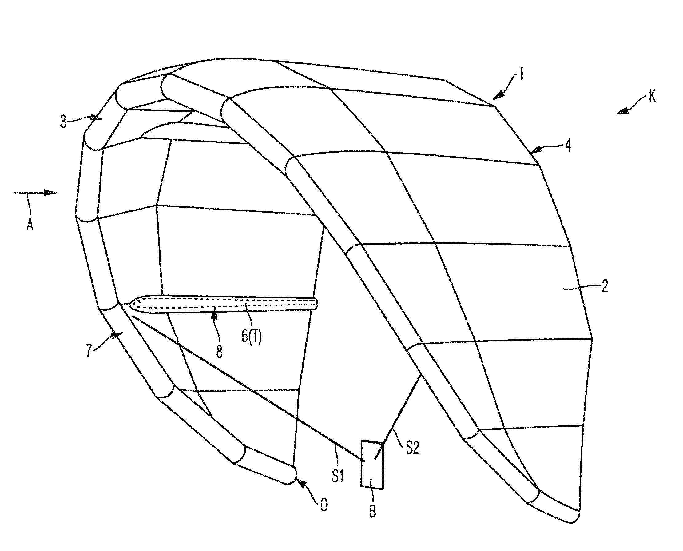
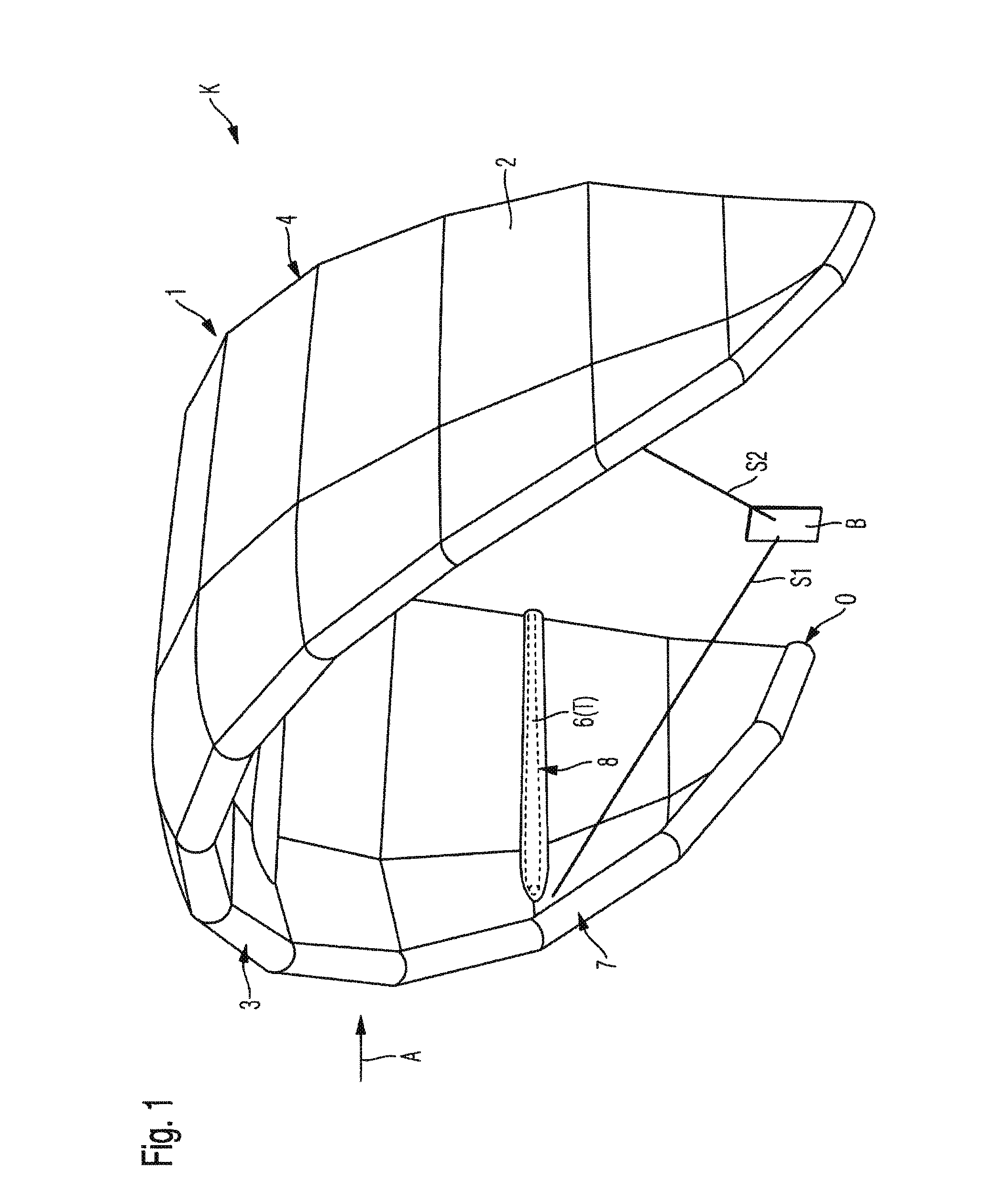
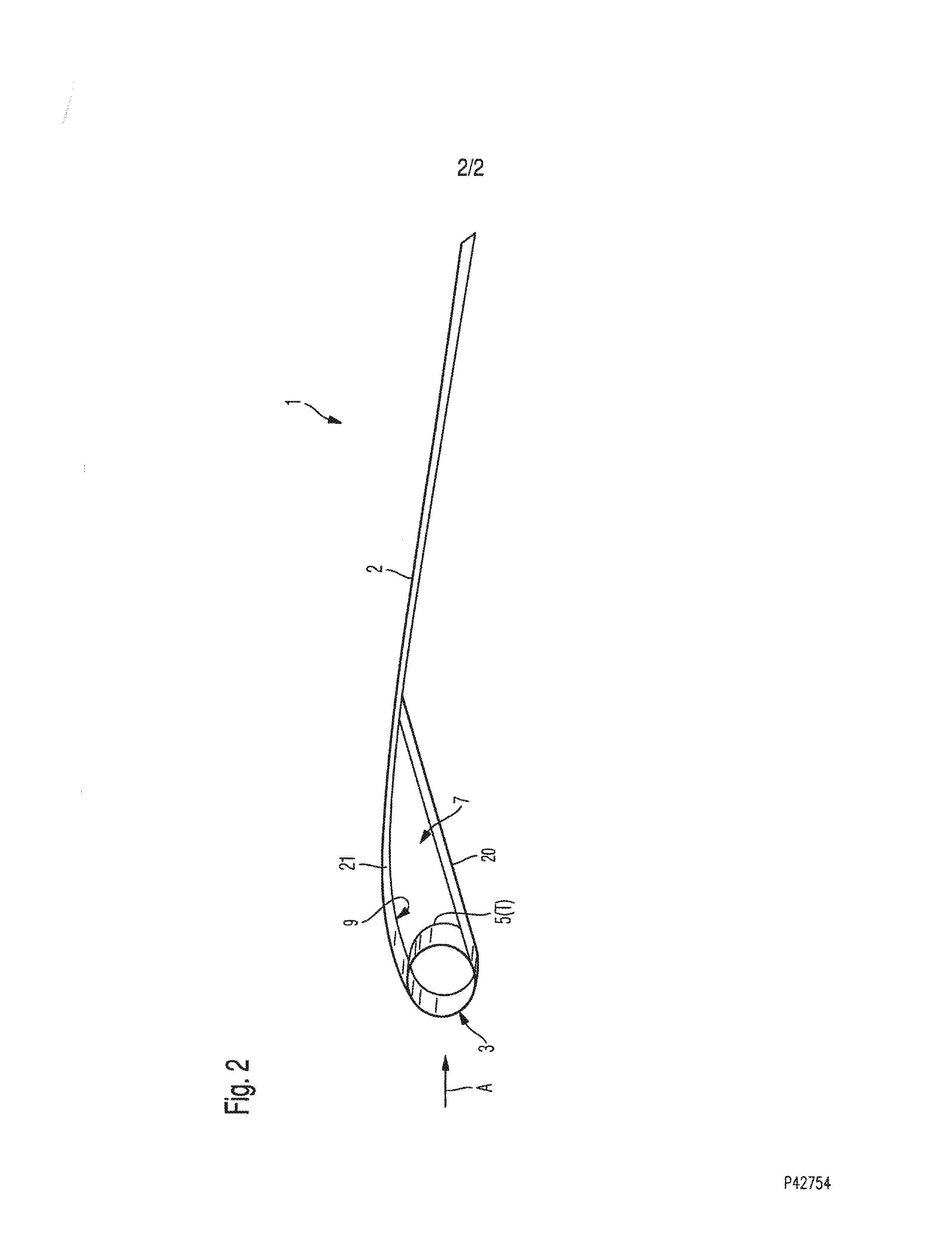
[0022]FIGS. 1 and 2 show a control sail 1 and a kite K having a control sail 1 according to one exemplary embodiment of the invention. The control sail 1 has an airfoil 2 which is made of a suitable material, preferably a ripstop fabric such as polyester ripstop, for example. The airfoil 2 has a leading edge 3 which preferably extends along the entire front edge of the airfoil 2. In addition, the airfoil 2 has a trailing edge 4 which extends along the entire rear edge of the airfoil 2. The airfoil 2 extends between the leading edge 3 and the trailing edge 4.

[0023]Furthermore, the control sail 1 has a tube system T. The tube system T has a front tube 5 which extends along the leading edge 3, preferably along the entire leading edge 3. In addition, the tube system T has at least one transverse tube 6 (in FIG. 1, four transverse tubes 6, one of which is schematically illustrated) which extends between the leading edge 3 and the trailing edge 4, preferably essentially over the entire ex...


PUM


Abstract

A control sail for a kite has an airfoil with a leading edge and a trailing edge, and a tube system comprising a front tube which extends along the leading edge and at least one transverse tube which extends between the leading edge and the trailing edge. The front tube is situated in a freely movable manner within a chamber which extends along the leading edge of the airfoil whereby an aerodynamically advantageous profile at the leading edge may be continuously maintained, even when the angle of attack of the control sail changes. The invention further relates to a kite having a control sail according to the invention, with control lines connected to the control sail.

Description

CROSS REFERENCE TO RELATED APPLICATIONS[0001]This application claims priority of German Patent Application Serial No. DE 10 2012 018 187.6, filed on Sep. 13, 2012.STATEMENT REGARDING FEDERALLY SPONSORED RESEARCH OR DEVELOPMENT[0002]N / ACOPYRIGHT NOTICE[0003]A portion of the disclosure of this patent document contains material that is subject to copyright protection. The copyright owner has no objection to the facsimile reproduction by anyone of the patent document or patent disclosure as it appears in the Patent and Trademark Office patent file or records, but otherwise reserves all rights whatsoever.BACKGROUND OF THE INVENTION[0004]1. Field of the Invention[0005]The present invention relates to a control sail for a kite, having an airfoil and a tube system, and a kite having such a control sail.[0006]2. Description of Related Art[0007]Kites having these types of control sails, also referred to as tube kites, are known from the prior art. DE 102 13 403 A1 and DE 10 2009 009 305 A1 ea...

Claims


Application Information

Patent Timeline
Patent Type & Authority Applications(United States)
IPC IPC(8): B64C31/06
CPCB64C31/06B64C2031/065B63H8/16
Inventor STIEWE, PETER
Owner RIDE BEST
Why Eureka
Try Eureka