
Electric Lamp Having an Automatic Light Regulation

a technology of automatic light regulation and electric lamps, which is applied in the direction of electrical appliances, lighting and heating equipment, electric circuit arrangements, etc., to achieve the effect of avoiding disturban

Inactive Publication Date: 2014-03-13
ZEDEL CORP
View PDF5 Cites 38 Cited by
  • Summary
  • Abstract
  • Description
  • Claims
  • Application Information

AI Technical Summary

Benefits of technology

The present invention is a headlamp with an advanced control mechanism to improve efficiency and comfort for the lamp holder. It provides improved method for controlling the light intensity to increase the ease of use of the lamp while rendering the regulation less sensitive to the parasitic light sources. The headlamp has new functionalities and can be used in a wide number of applications. The control circuit adjusts the power of the light beam based on only values of L=M1−M3 and E=M1−M2, excluding the intervention of the ambient light. This way, it is possible to avoid disturbance resulting from the ambient light (car lights for example).

Problems solved by technology

The problem to solve is to propose a dynamic or reactive lamp which still is cheap to manufacture.

Method used


Image

  • Electric Lamp Having an Automatic Light Regulation
  • Electric Lamp Having an Automatic Light Regulation
  • Electric Lamp Having an Automatic Light Regulation

Examples


second embodiment

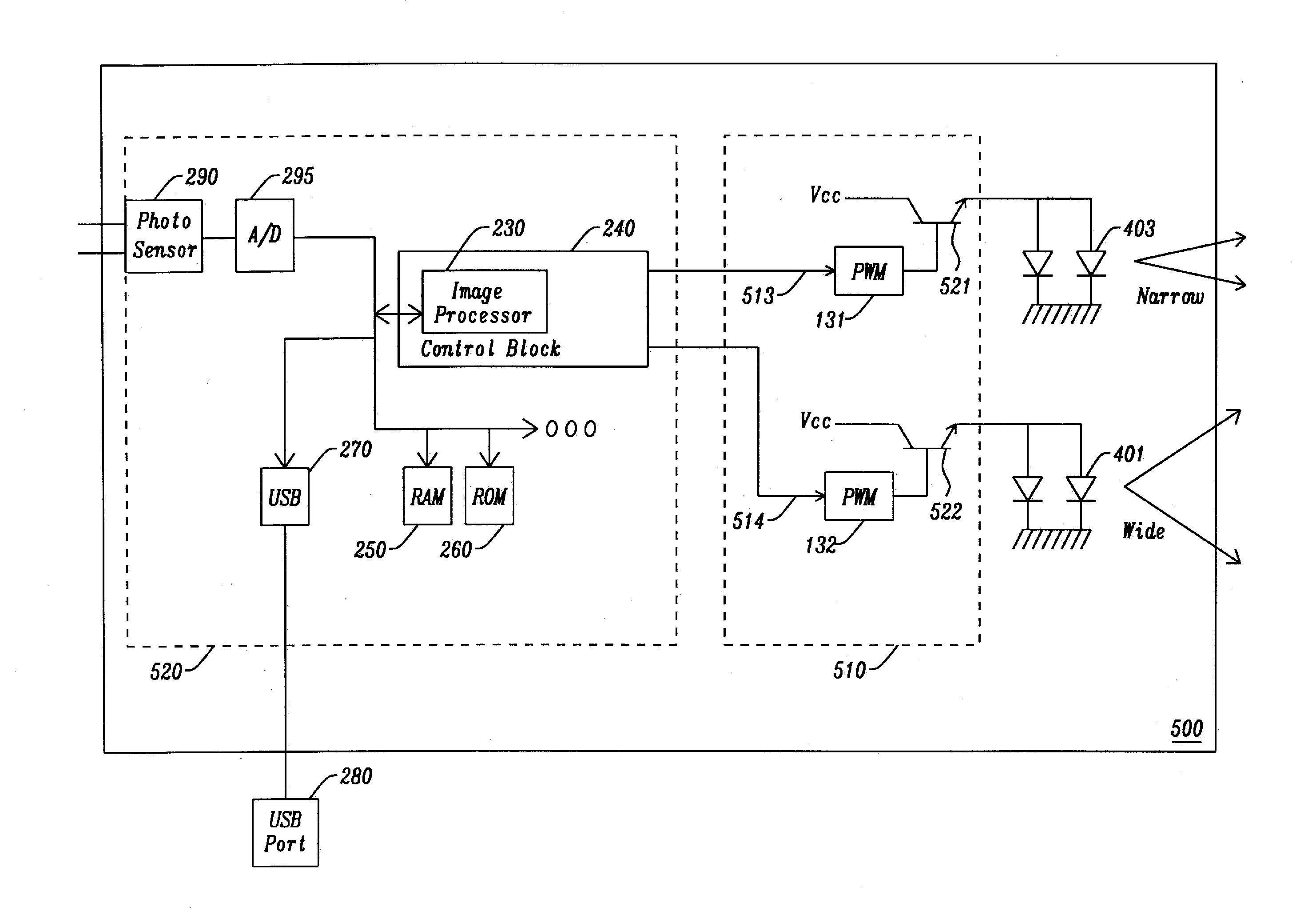
[0086]It will now be described in relation to FIG. 5, a headlamp having one single photo sensor 290, but used for the generation of two light beams generated by the LEDs 403 and 401, respectively narrow and wide.

[0087]The lamp 500 includes a power unit 510 comprising a power source, such as a battery (not shown in the figure), which generates a supply voltage Vcc, and two power switches, respectively 521 and 522, for the powering in current of LED diodes 403 and 401, and respectively controlled by circuits 131 and 132, implementing the s PWM modulation. Switches 521 and 522 are for instance of the type semiconductor such as a bipolar transistor, an FET (Field Effect Transistor) or MOS (Metal Oxide Semiconductor) or MOSFET.

[0088]Both circuits 521 and 522 are respectively controlled by the control information or to control signals 513 and 514 generated by integrated control unit 240 integrated within control unit 520.

[0089]This is only one illustrative embodiment, and a skilled man ma...

third embodiment

[0113]It is now be described with reference to FIG. 7, a third embodiment in which the power unit 510 of FIG. 5 is used for powering a set of two diodes 501 and 503 (only one being shown for each diode beam) having slightly different axes. The two sets of diodes 501-503 are powered through the power unit 110, respectively via leads 502 and 504 under control of control unit 520.

[0114]If FIG. 7 illustrates one embodiment with only two series diodes and hence only two separate axes 11 and 12, it is clear that a man skilled in the art I can adapt the invention so as to produce a number of light beams and a number of axes being superior than two.

[0115]In the embodiment that is illustrated, it should be observed that control unit 520 generates two control information or control signals, respectively, 513 and 514, for the purpose of controlling the power emitted by the corresponding series of LEDs, ie LED 501 and 503.

[0116]From a dynamic point of view, as above for the first two embodiment...


PUM


Abstract

A portable lamp, such as a headlamp, comprising:a light source comprising one or more sources for generating at least one light beam;means for controlling the brightness of said at least one beam in response to a control information or a control signal;a control unit for the purpose of generating said control information or said control signal;wherein said control unit comprises at least a photo sensor and a regulation circuit controlling a switch-off phase of one or more beams during a period not visible to the holder of the lamp, said switch off phase being combined with at least one measure of diversity made by means of said photo sensor(s) on the reflective ambient environment.

Description

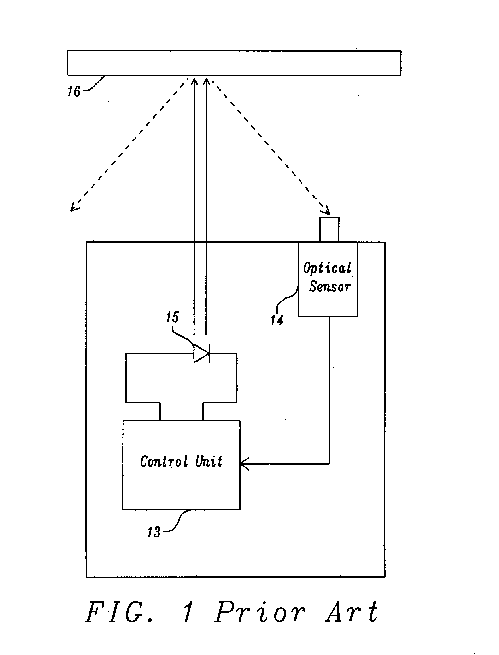
TECHNICAL FIELD[0001]The present invention relates to the field of portable electric lamps including a portable electric lamp with an automatic lighting control.BACKGROUND[0002]The Applicant of the present application has marketed a portable lamp, of the type headlamp, with a so-called “reactive” or “dynamic” lighting which is described in patent application WO2009 / 133309. Briefly, as illustrated in prior art FIG. 1, there is a headlamp having at least one light emitting diode 15 and a LED type optical sensor 14 located in the vicinity and for sensing a signal representative of the light reflected by the surface of an object illuminated by the lamp 16. A control circuit 13 processes the signal for the purpose of automatically controlling the power of the LED according to a predetermined threshold. In this way, an automatic adjustment of the light beam emitted by the lamp can be achieved without any manual action to adapt the light to the environment, while managing energy consumptio...

Claims


Application Information

Patent Timeline
Patent Type & Authority Applications(United States)
IPC IPC(8): B60Q1/14H05B44/00
CPCB60Q1/1423H05B47/11Y02B20/40F21L4/00F21V23/0414F21V23/0442F21Y2115/10H05B45/12H05B44/00H05B47/105
Inventor GENTHON, FABIENPELLAT-FINET, ROMAIN
Owner ZEDEL CORP
Learn More