E-field shield for wireless charger

a wireless charger and shielding technology, applied in the direction of battery overheat protection, safety/protection circuit, transportation and packaging, etc., can solve the problems of wasting heat of the charger coil, no conductive loop established above the coil, and the temperature rise of the charger surface that contacts the chargeable device, etc., to achieve enhanced heat sink function, reduce the effect of waste heat, and enhance the effect of e-field shielding pattern

Active Publication Date: 2014-03-13
POWERMAT TECHNOLOGIES +1
View PDF2 Cites 28 Cited by
  • Summary
  • Abstract
  • Description
  • Claims
  • Application Information

AI Technical Summary

Benefits of technology

[0036]In some embodiments of the invention, the E-field shield assists in the dissipation of the charger coil waste heat by providing a solid copper pattern in areas of the shield that are not directly above the coil. The effectiveness of the E-field shield pattern is enhanced if the E-field shield is made of a material that is highly electrically conductive. Moreover, significant advantages are achieved if the material is highly thermally conductive for enhancing the heat sink function. Copper is an excellent material for both parameters, as it is an excellent electrical and thermal conductor. The same vias that are used to ground the shield conductor can also serve as thermal vias to the grounded aluminum heat sink in the charger that is

Problems solved by technology

However, it is expensive, and inefficient from the standpoint of power utilization, to eliminate the harmonics of the primary signal that spill over into the AM band and interfere with AM radio reception.
However, the prior art does not seem to address the particular concerns of an automotive application of wireless charging and its interference with the AM radio reception.
Another problem

Method used


Image

  • E-field shield for wireless charger
  • E-field shield for wireless charger
  • E-field shield for wireless charger

Examples


Embodiment Construction

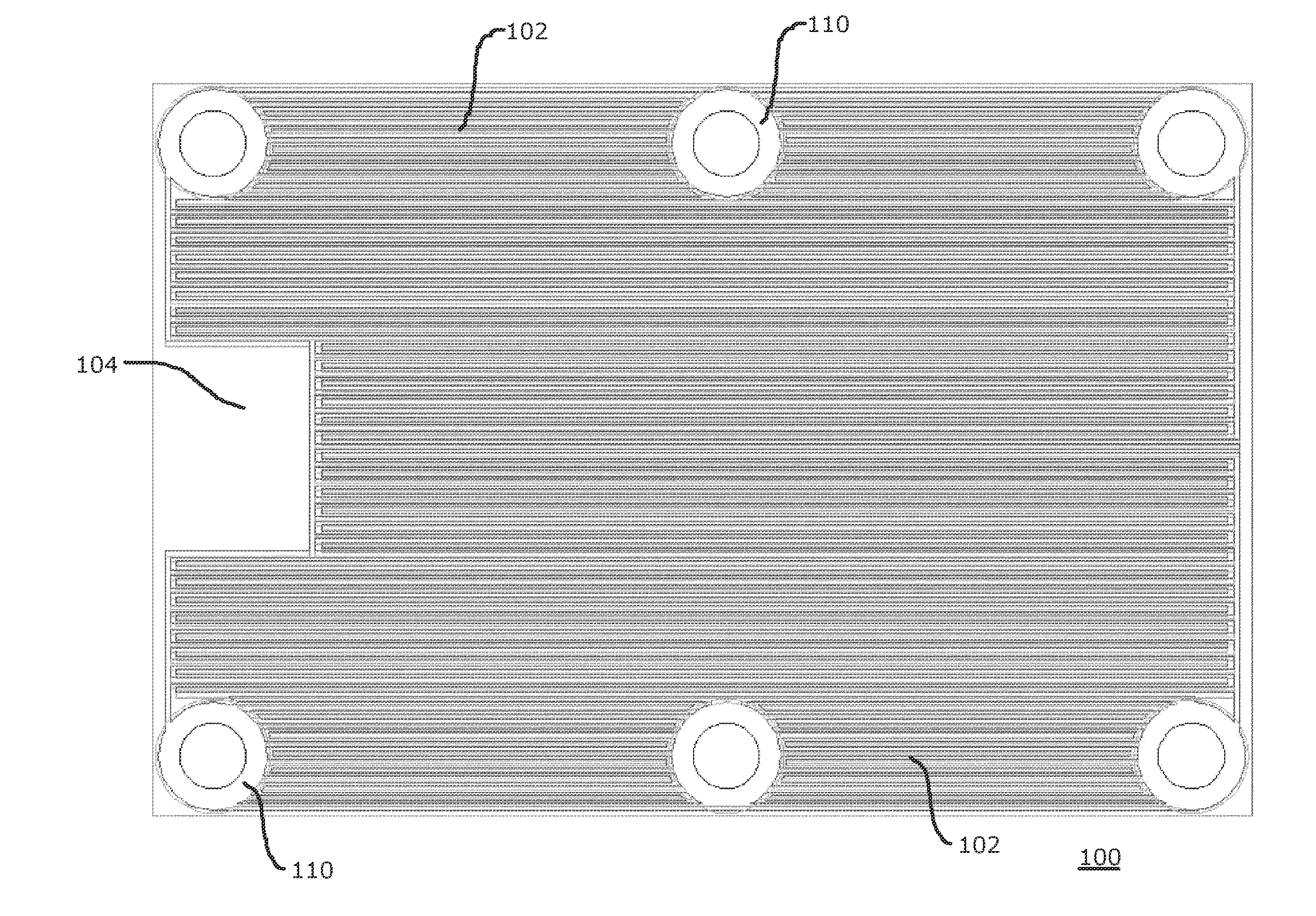
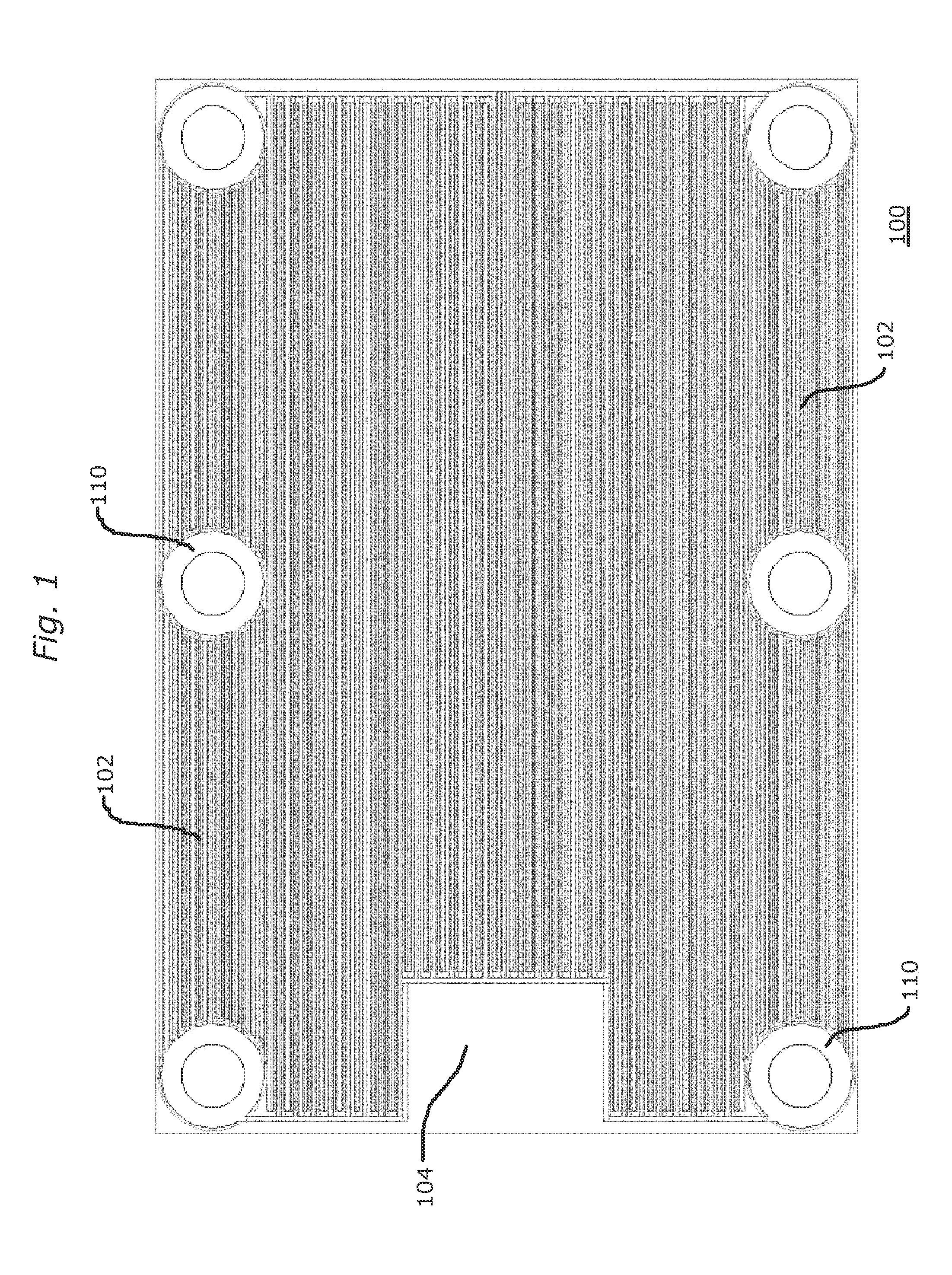
[0050]FIG. 1 is a plan representation of one side of an E-field shield 100 constructed in accordance with the principles of the invention, and depicts plural electrically conductive traces 102 arranged longitudinally on a circuit board 104. In this specific illustrative embodiment of the invention, circuit board 104 is configured for use with a wireless charger (not shown) for a handheld device (not shown). Electrically conductive traces 102 are electrically coupled to one another at solid patterns 110, and do not form, in this embodiment, any closed loops. The solid patterns, in this embodiment, are formed of copper and are arranged so as not to be located in the region (not specifically designated) of circuit board 104 that would be near the charging coil (not shown in this figure) of the wireless charger.

[0051]Electrically conductive traces 102 are separated from one another by a distance that is, in some embodiments, responsive to the frequency of the electrical energy that is d...


PUM


Abstract

A shielding arrangement for preventing AM radio interference when a wireless charger is used in a vehicle has a plurality of parallel conductors arranged at a distance from one another responsive to a frequency desired to be attenuated. An interconnection arrangement includes a solid conductive junction and connects the conductors to one another without forming loops, and to ground. The conductors are traces disposed on a PCB. Additional parallel conducts are disposed on the other side of the PCB at an orthogonal orientation with respect to the first conductors. The spacing between the conductors is determined in response to the frequency desired to be attenuated, as well as frequencies thereabove that are desired to be propagated therethrough, such as mobile telephone signals. The solid conductive junction that is disposed on the printed circuit board is electrically and thermally conductive, such as copper.

Description

BACKGROUND OF THE INVENTION[0001]1. Field of the Invention[0002]This invention relates generally to electrical power systems that produce undesired electromagnetic fields and heat, and more particularly, to a shielding arrangement that is particularly useful in charging systems for chargeable devices, wherein the propagation of electromagnetic fields and heat is attenuated, but magnetic fields are permitted to pass with minimal eddy current losses. This invention relates generally to electrical power systems that produce undesired electromagnetic fields and heat, and more particularly, to a shielding arrangement that is particularly useful in charging systems for chargeable devices, wherein the propagation of electromagnetic fields and heat is attenuated, but magnetic fields are permitted to pass with minimal eddy current losses.[0003]2. Description of the Related Art[0004]Wireless charging systems transfer energy between a primary and secondary coil by creating a time variant magne...

Claims


Application Information

Patent Timeline
IPC IPC(8): H05K9/00H02J7/00
CPCH02J7/00H05K9/00H01F38/14H02J7/00309H01F27/36H01F27/363H02J50/20H02J50/70H02J50/10H02J7/04
Inventor CHILES, KAREN LEEBALINT, III, JOHN ROBERTGRADY, KEVINGREENWALD, OOLAO'BRIEN, GARY
Owner POWERMAT TECHNOLOGIES
Why Eureka
Try Eureka