Low Ripple Step-Up/Step-Down Converter

a converter and step-down technology, applied in the direction of dc-dc conversion, power conversion systems, instruments, etc., can solve the problems of high frequency, affecting the output voltage of rf signals, and not being suitable for rf applications wherein the output voltage is amplitude modulated, etc., to achieve low ripple, reduce the effect of ripple and high bandwidth

Active Publication Date: 2014-03-13
TELEFON AB LM ERICSSON (PUBL)
View PDF18 Cites 62 Cited by
  • Summary
  • Abstract
  • Description
  • Claims
  • Application Information

AI Technical Summary

Benefits of technology

[0020]To improve the situation, a first aspect of the present invention relates to a multi-level Step-Up/Down converter for low ripple, high bandwidth. It allows for tracking applications such as envelope-tracking or polar modulation in radio frequency power amplifiers (RF PAs). Such a multi-level

Problems solved by technology

Low ripple behaviour is however a stringent parameter, especially for DC-DC converters dedicated to supply power for radio-frequency (RF) applications, because the ripples may create interferences, with RF signals.
This approach is currently used for classic DC-DC converters, where the output voltage is not varying (the output voltage is a DC value converted from Vbat), but this is not appropriate for RF applications wherein the output voltage is amplitude modulated.
But, nonetheless, this solution presents some issues.
Furthermore, the high frequency may create interferences with RF signals that

Method used


Image

  • Low Ripple Step-Up/Step-Down Converter
  • Low Ripple Step-Up/Step-Down Converter
  • Low Ripple Step-Up/Step-Down Converter

Examples


first embodiment

of a Multilevel Charge Pump:

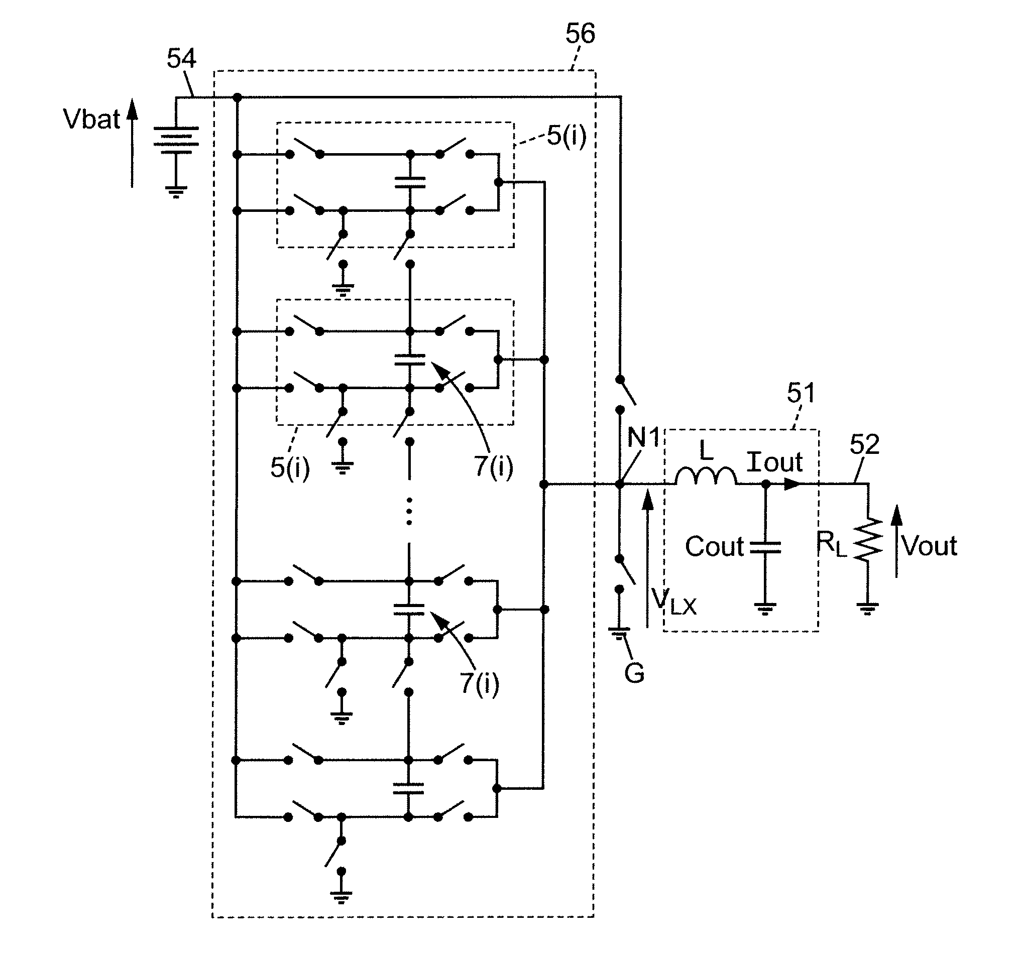
[0085]Referring to FIGS. 5A to 5E there is shown therein a schematic view of an embodiment of a multilevel charge pump according to the invention.

[0086]FIG. 5A illustrates a global schematic view of the charge pump that represents every connection with switches. FIG. 5B to 5E illustrates schematics of the charge pump in different modes of operation, and as such, neither the interrupted connections nor the switches are represented.

[0087]The multilevel charge pump 56 comprises an input terminal 54 adapted to receive an input signal having an input voltage Vbat and an output terminal 52 of the charge pump adapted to be connected to a first circuit node N1, and to output an intermediate output voltage VLX, converted from the input voltage Vbat, at the first circuit node N1 (FIG. 5A). The charge pump comprises further a main module connected between the input terminal and the output terminal of the charge pump.

[0088]The main module 56′, the input terminal 54 a...


PUM


Abstract

There is described a device for converting an input signal having a given input voltage (Vbat) value (Vbat) into an output signal having an output voltage (Vout) (Vout) different from the input voltage (Vbat). The device comprises a main module (56), arranged between an input terminal (54) and a first circuit node (N1), The device is adapted to output at the first circuit node (N1) a pulse-width-modulated (PWM) signal switching between a first voltage value and a second voltage value, defining a switching range (SR(i)), by switching successively between a first mode of operation and a second mode of operation. The switching range (SR(i)) of the pulse width modulation (PWM) has an amplitude, calculated as the absolute difference between the first and the second voltage value, inferior or equal to Vout half the input voltage (Vbat).

Description

BACKGROUND[0001]1. Technical Field[0002]The present invention generally relates to devices and methods for using DC-DC converters and for converting a continuous signal of a given value into another signal of another value, for example for envelope tracking or polar modulation for radio frequency power amplifiers. The present invention finds applications in particular in electronic portable devices such as for mobile phones, digital walk-men, portable computers, PDA, etc.[0003]2. Related Art[0004]The approaches described in this section could be pursued, but are not necessarily approaches that have been previously conceived or pursued. Therefore, unless otherwise indicated herein, the approaches described in this section are not prior art to the claims in this application and are not admitted to be prior art by inclusion in this section.[0005]Multiple supply voltages have become increasingly common due to the coexistence of low-power digital circuits, high-speed digital circuits, an...

Claims


Application Information

Patent Timeline
IPC IPC(8): H02M3/02
CPCH02M3/07H02M3/02H02M2003/072H02M3/1584H02M3/158H02M1/007H02M1/0095H02M3/072H02M3/077
Inventor ARNO, PATRIK
Owner TELEFON AB LM ERICSSON (PUBL)
Why Eureka
Try Eureka