Adaptor for connecting an electronic device having a camera to an optical device

a technology of adaptors and optical devices, which is applied in the direction of couplings, instruments, machine supports, etc., can solve the problems of not being able to conform and grip onto the cylindrical plastic ring may not have a snug and fitted grip, and the construction does not allow for the ability to conform and grip on these types of housings. , to achieve the effect of convenient us

Active Publication Date: 2014-03-13
CARSON OPTICAL
View PDF25 Cites 17 Cited by
  • Summary
  • Abstract
  • Description
  • Claims
  • Application Information

AI Technical Summary

Benefits of technology

[0010]For example, it is objectives of the present invention to provide an improved adaptor device that adequately fits a range of optical devices, while still providing a secure and self-aligned connection to the electronic device having a camera. Said adaptor device is easier to use and generally more universal than prior art constructions.
[0012]Another objective of the present invention is to develop a adaptor device which does not require user adjustments to properly center or align the optical device. Furthermore, it would not require the user to adjust any knob or clamp so that the optical device is held tight by the adaptor device.

Problems solved by technology

There is prior art regarding the connection of cameras or electronic devices having a camera to an optical device, but none of these prior art adaptor devices utilize a simple, yet self-centering and fitted connection that is capable of fitting to a range of sizes and types of optical devices.
Furthermore, the fixed diameter, cylindrical plastic ring may not have a snug and fitted hold on optics with a smooth rubber, plain plastic or metal housing or housing that doesn't have a matching contour to the adaptor.
The construction does not allow for the ability to conform and grip onto these types of housings.
Therefore, the structure of such prior art is limiting not only to size but material and contour of the housing.
Other similarly limited approaches use threads on the adaptor to match up with threads on the optical device.
This becomes a complicated procedure of adjustments for the users, and is very time consuming and frustrating for anyone using the device on multiple optical devices.
Furthermore, the prior art can not meet these requirements, especially without the need for adjustments by the user, such as tightening down a clamp or centering the axes manually.

Method used


Image

  • Adaptor for connecting an electronic device having a camera to an optical device
  • Adaptor for connecting an electronic device having a camera to an optical device
  • Adaptor for connecting an electronic device having a camera to an optical device

Examples


Embodiment Construction

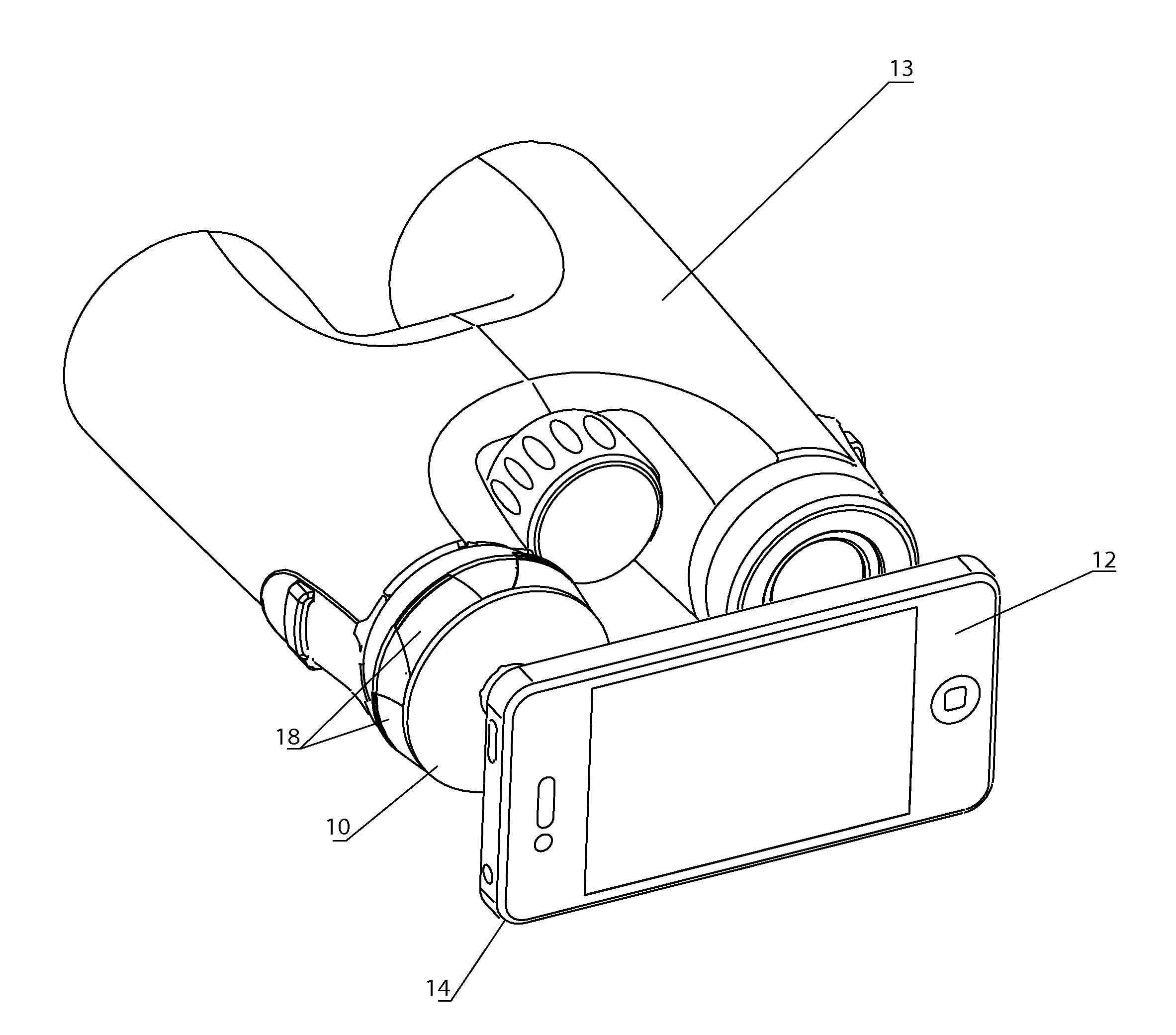
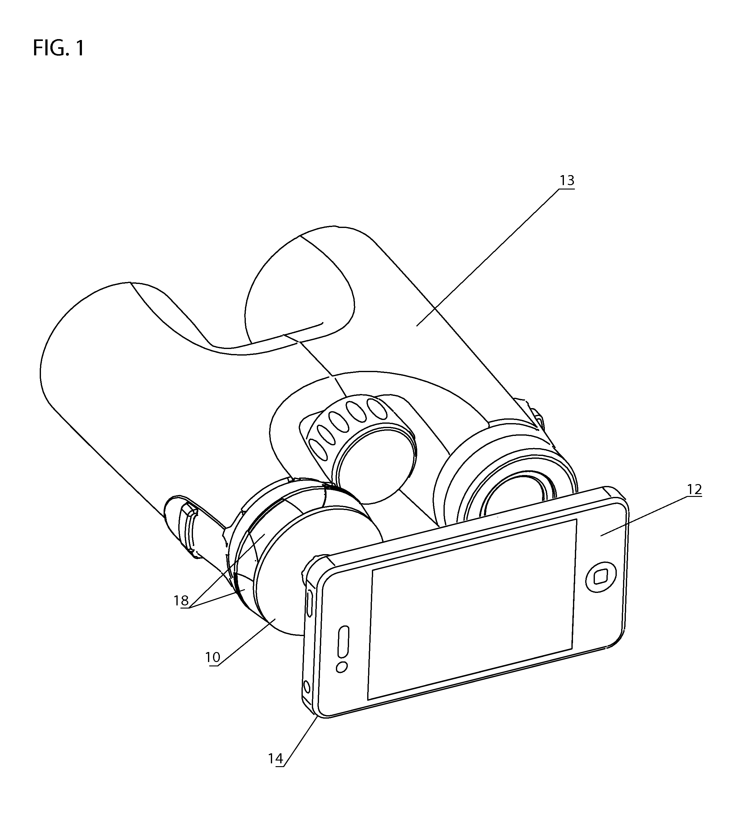
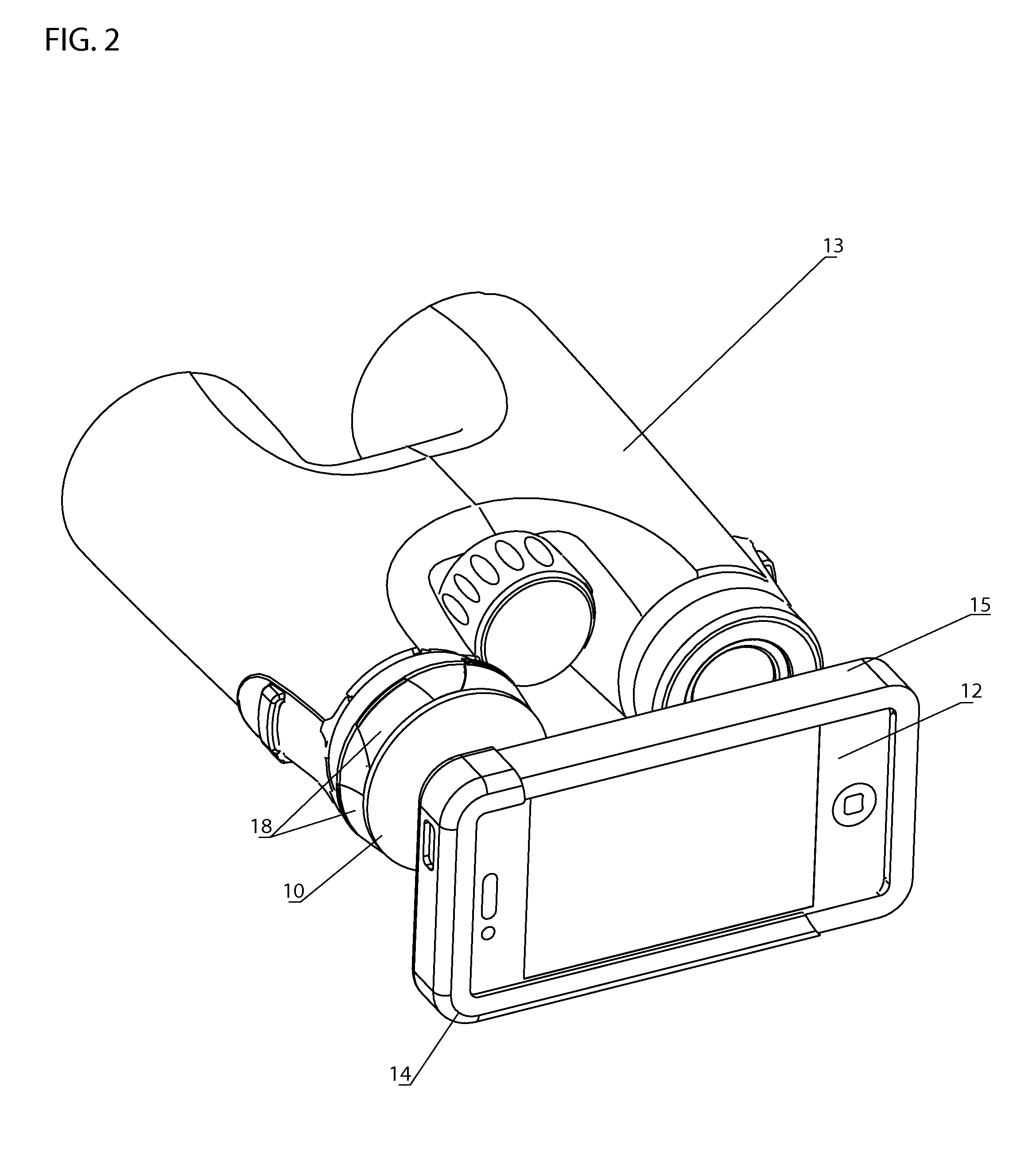
[0028]The preferred embodiment of the adaptor device in FIG. 1 having a main body 10, and a plurality of protrusions 18. The optical device 13 shown is binoculars, wherein the adaptor device is aligned with the binoculars' first optical axis, or if in the case of a monocular, the sole optical axis. The device is depicted in a coupled state to an electronic device comprising a camera 12. In this example shown, the electronic device having a camera 12 is a smartphone attached via physical, mechanical, magnetic, or a combination thereof means to the adaptor device. For example, the main body could include an array of magnets that mates with a matching set of magnets that are part of the electronic device. However, the adaptor device may also be coupleable to the electronic device indirectly by utilizing additional components, such as a holder or case for the electronic device. In the embodiment shown in FIG. 2, the holder is a plastic sleeve 14 maintaining a grip around a rubber case 1...


PUM

PropertyMeasurementUnit
diameteraaaaaaaaaa
thicknessesaaaaaaaaaa
opticalaaaaaaaaaa

Abstract

This invention comprises an adaptor device for connecting an electronic device having a camera to a range of optical devices, including but not limited to binoculars, monoculars, riflescopes, spotting scopes, telescopes, and microscopes. This adaptor device has a plurality of protrusion that provide a self-centering and fitted connection between the electronic and optical device, so that the optical axes are aligned so that the user may take images or video on their electronic device through the optical device. The structure of the adaptor device allows the adaptor to fit a range of differently sized optical device, denoted by the diameter of the eyepiece end of the optical device.

Description

FIELD OF THE INVENTION[0001]There are many common optical devices, such as binoculars, monoculars, riflescopes, spotting scopes, telescopes, and microscopes, which do not have image recording capabilities, such as a built-in camera. These types of optical devices each have an eyepiece end, the end closest to the observer and a objective end, the end closest to the object being viewed. The external housing of the eyepiece lens end, also commonly referred to as an eyecup, has an approximately cylindrical shape mirroring the cylindrical shape and size of the eyepiece lens. Each type and size of optical device corresponds to a range of diameters of the external cylindrical housing for eyepiece lens end.[0002]In order to having imaging recording capabilities with these optical devices, some versions of these optical devices have been made with integrated cameras or attachment means to a full sized DSLR camera but the result is always a bulky, heavy and expensive design.[0003]Since many c...

Claims


Application Information

Patent Timeline
Patent Type & Authority Applications(United States)
IPC IPC(8): F16B21/06F16M13/02
CPCF16M13/022F16B21/065G03B17/48Y10T29/49895Y10T29/49876G03B17/566F16M13/02
Inventor HYERS, MICHELLE
Owner CARSON OPTICAL
Why Eureka
Try Eureka