Turbomachine rotor with a means for axial retention of the blades

Active Publication Date: 2014-03-13
SN DETUDE & DE CONSTR DE MOTEURS DAVIATION S N E C M A
View PDF4 Cites 5 Cited by
  • Summary
  • Abstract
  • Description
  • Claims
  • Application Information

AI Technical Summary

Benefits of technology

[0014]The solution of the invention therefore consists in eliminating

Problems solved by technology

The bulkiness of the screwed connection between the wedge and the lock therefore means that the rear shell ring of the rotor nose cowl has to avoid the area.
This is because the rear part of such

Method used


Image

  • Turbomachine rotor with a means for axial retention of the blades
  • Turbomachine rotor with a means for axial retention of the blades
  • Turbomachine rotor with a means for axial retention of the blades

Examples


Embodiment Construction

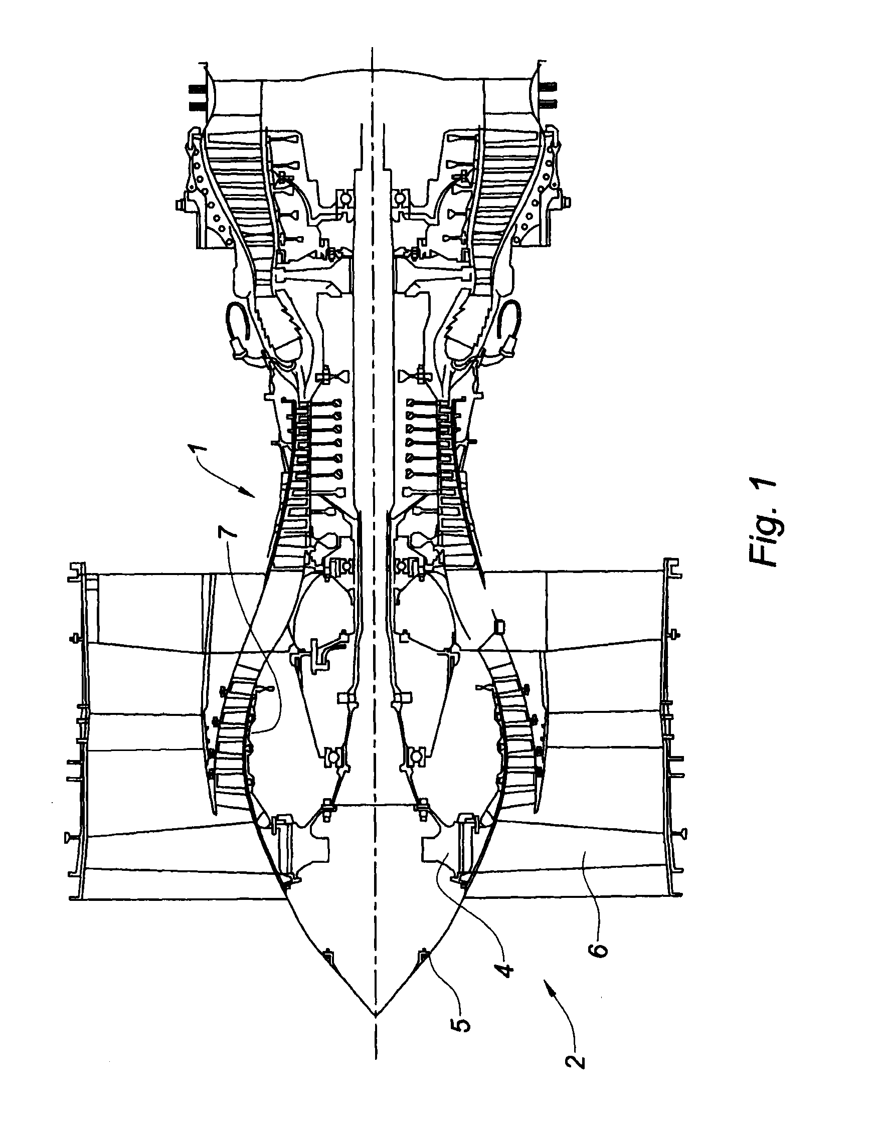
[0037]The turbojet engine of FIG. 1 is a twin flow (bypass) engine with a front fan 2 comprising a fan disk 4 on which there are fan blades 6 retained by their roots in pockets formed in the rim. The disk is mounted with overhang on the low-pressure shaft which likewise supports the drum 7 of the low-pressure or boost compressor immediately downstream of the disk and to which it is secured. A component 5 of conical overall shape is fixed on the upstream side to the fan disk; this component has an essentially aerodynamic function of guiding the stream of air toward the inlet of the engine.

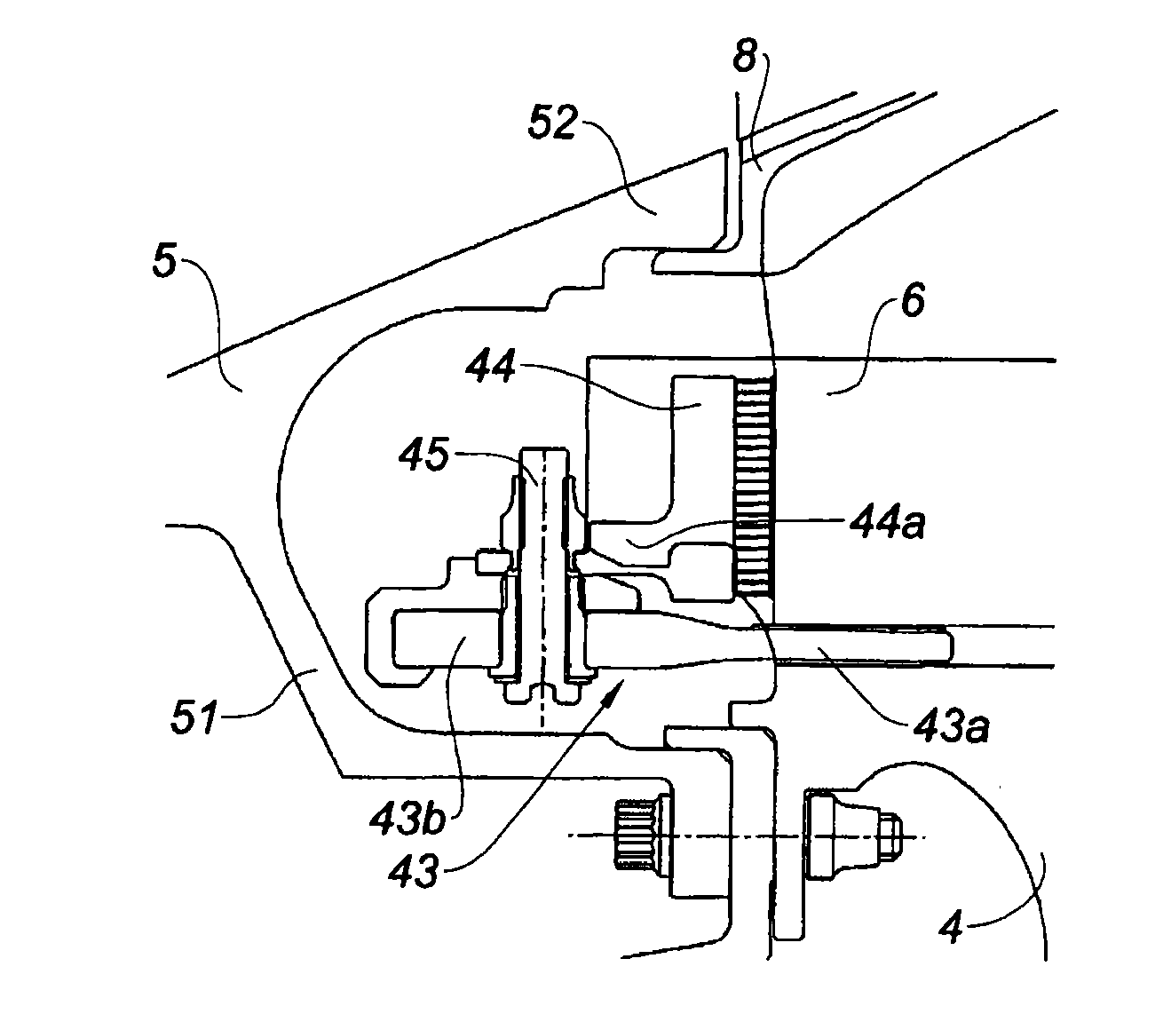
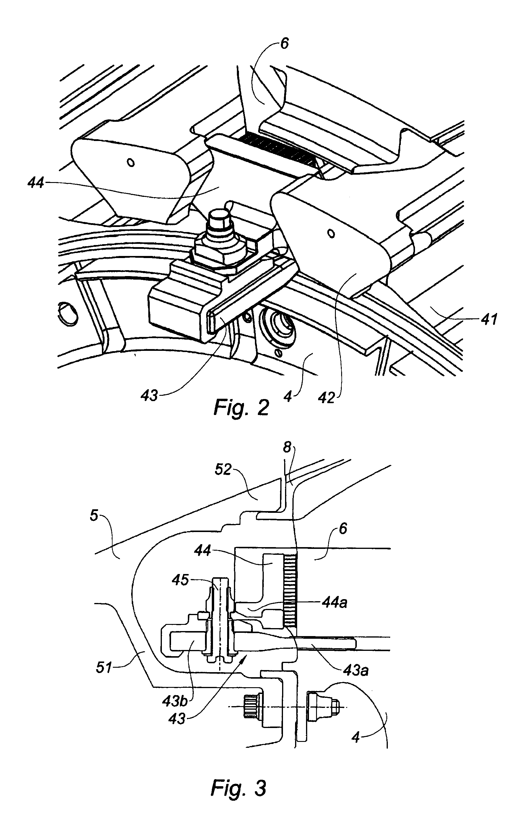
[0038]FIGS. 2 and 3 show the mounting of a fan blade 6 in a pocket 41 of the fan disk, according to the prior art. An axial wedge 43 is slipped under the root of the blade in order to keep the blade retained radially in its pocket and a lock 44 perpendicular to the wedge 43 is slipped into notches formed in the side walls of the pocket on the upstream side of the disk. The axial wedge comprises a pa...


PUM


Abstract

A rotor of a turbomachine, such as a multi-flow turbojet engine fan, has a disc including, on the rim thereof, substantially axial slots with a dovetailed cross-section, and blades mounted individually in the slots, an axial wedge positioned between the root of the blades and the bottom of the slots, and a transverse lock providing upstream axial immobilization of the blades in the slot thereof. The lock is guided in radial notches formed in the flanks of the slots and radially supported against the wedge. The axial wedge is immobilised in the upstream direction, butting up against a transverse annular component secured to the disc.

Description

TECHNICAL FIELD OF THE INVENTION[0001]The present invention relates to the field of turbomachines, more particularly that of multiflow turbofan engines with the fan at the front and is concerned with the axial locking of the blades housed in axial pockets or grooves on the rim of a rotor disk. It is essentially concerned with the locking of the fan blades in their housing on the fan disk.PRIOR ART[0002]A multiflow turbojet engine comprises a gas turbine engine driving a fan generally situated at the front of the engine. A fan conventionally comprises a rotor disk provided with a plurality of radial fan blades spaced apart from one another circumferentially and fixed in individual pockets formed on its rim. The pockets are oriented substantially axially and have a dovetail cross section. Their shape complements that of the blade roots to hold the latter in place when the blades are subjected to the centrifugal forces as the disk rotates. The blades are fitted individually by introduc...

Claims


Application Information

Patent Timeline
IPC IPC(8): F01D5/30
CPCF01D5/3038F01D5/323F01D11/008F04D29/322F05D2220/36
Inventor MARLIN, FRANCOIS MARIE, PAULIMBOURG, FREDERICQUEANT, DIDIER
Owner SN DETUDE & DE CONSTR DE MOTEURS DAVIATION S N E C M A
Why Eureka
Try Eureka