All-solid-state cell

a cell and solid-state technology, applied in the field of all-solid-state cells, can solve the problems of battery capacity that cannot be high, lithium ions cannot be emitted and inserted, battery can only be improved only to a limited extent, etc., and achieve high battery capacity and high resistance

Inactive Publication Date: 2014-03-13
NGK INSULATORS LTD
View PDF2 Cites 54 Cited by
  • Summary
  • Abstract
  • Description
  • Claims
  • Application Information

AI Technical Summary

Benefits of technology

[0012]In view of the above problems, an object of the present invention is to provide an all-solid-state cell, which does not have a high resistance against lithium ion emission from a negative electrode active material and lithium ion insertion into the material, and is capable of emitting and inserting a large amount of lithium ions in a high input / output process to achieve a high battery capacity.
[0023]The all-solid-state cell of the invention does not have a high resistance against the lithium ion emission from the negative electrode active material and the lithium ion insertion into the negative electrode active material. Therefore, the all-solid-state cell is capable of emitting and inserting a large amount of lithium ions in a high input / output process, and can achieve a high battery capacity.

Problems solved by technology

Consequently, the capacity of the battery can be improved only to a limited extent.
Therefore, in certain cases, only one, two, or three lithium ions can be simultaneously transferred, and the sieve may disadvantageously act as a resistance against the lithium ion emission from the negative electrode active material and the lithium ion insertion into the negative electrode active material.
Consequently, a large amount of the lithium ions cannot be emitted and inserted in a high input / output process, and the battery cannot have a high capacity.

Method used


Image

  • All-solid-state cell
  • All-solid-state cell
  • All-solid-state cell

Examples


modification example

[0090]In the above-described embodiment, in the layer 26 of the positive electrode active material 12, the (003) planes of the particles having the layered rock salt structure represented by the above general formula are oriented in the direction from the positive electrode layer 14 toward the negative electrode layer 20. Alternatively, as shown in FIG. 6, in an all-solid-state cell 10a according to a modification example, a layer 46 may be formed as the positive electrode active material 12 by mixing the particles having the layered rock salt structure represented by the general formula with the particles for the solid electrolyte layer, and by press-forming the mixture.

first example

[0091]In all-solid-state cells of Example 1, Example 2, Reference Example 1, and Comparative Example 1, changes of the volumetric energy densities with respect to various thicknesses of the solid electrolyte layer 16 were evaluated by a simulation test.

[0092]In First Example, when each all-solid-state cell was observed from above, both the horizontal and vertical lengths of the cell were 10 mm, and the thickness of the positive electrode active material 12 was 50 μm.

[0093]Characteristics of Example 1, Example 2, Reference Example 1, and Comparative Example 1 will be described below.

example 1

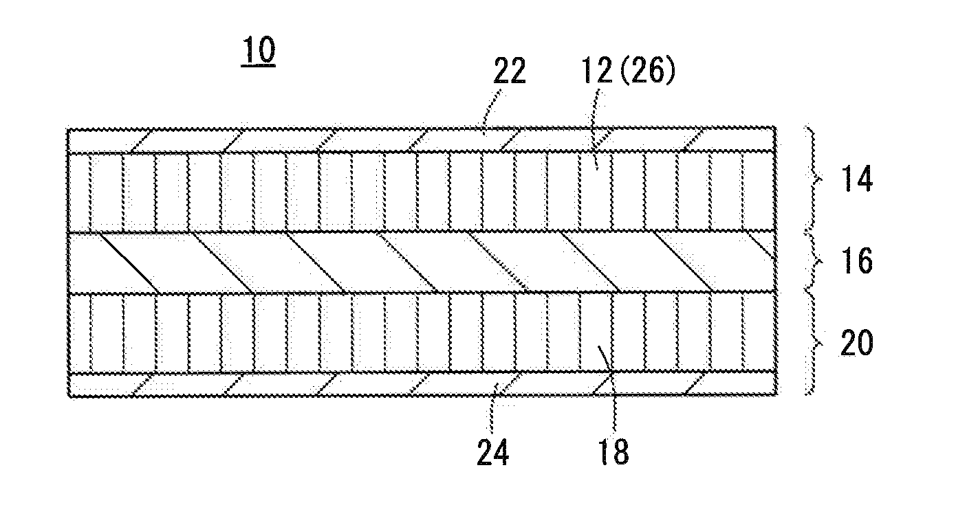
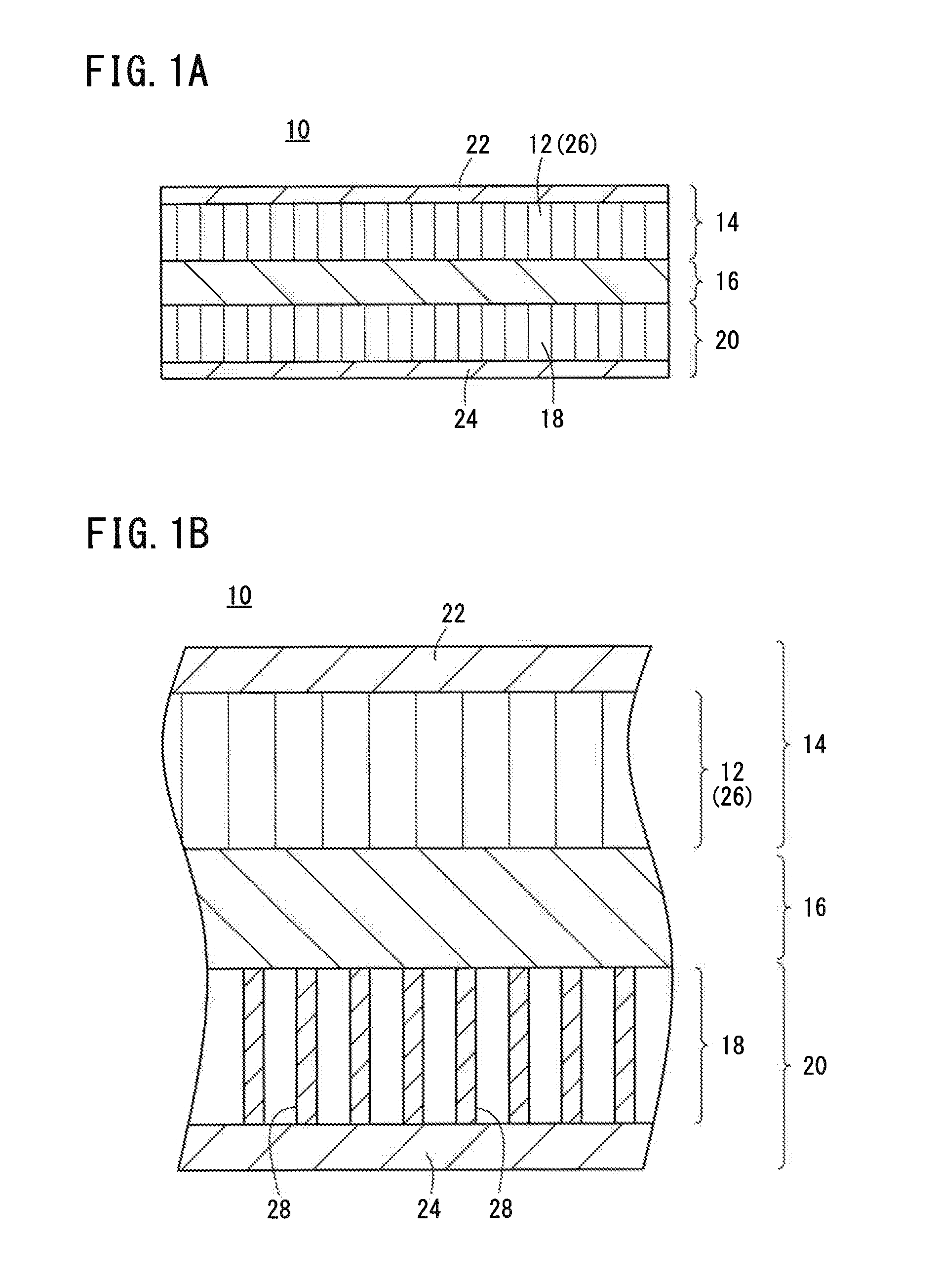
[0094]As shown in FIG. 7A, the all-solid-state cell of Example 1 had the same structure as the all-solid-state cell 10 of the above embodiment (see FIG. 1).

[0095]The positive electrode active material 12 contained layered rock salt-type particles having a composition of Li(Ni0.8Co0.15Al0.05)O2 (hereinafter simply referred to as NCA), and the (003) planes of the particles were oriented in the direction from the positive electrode layer 14 toward the negative electrode layer 20. The positive electrode active material 12 had a thickness of 50 μm.

[0096]The lithium ion conducting material in the solid electrolyte layer 16 contained garnet-type crystals having a composition of Li7La3Zr2O12 (hereinafter simply referred to as LLZ).

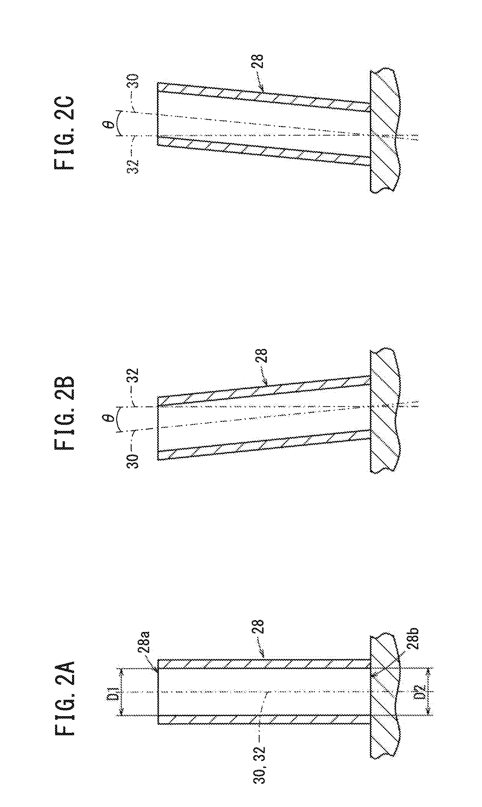
[0097]The negative electrode active material 18 contained a carbon nanotube array of a plurality of cylindrical carbon nanotube molecules 28 (hereinafter referred to as CNTA). The axes of the carbon nanotube molecules 28 were oriented in the direction from the pos...


PUM

PropertyMeasurementUnit
thicknessaaaaaaaaaa
angleaaaaaaaaaa
thicknessaaaaaaaaaa

Abstract

An all-solid-state cell has a positive electrode layer containing a positive electrode active material, a solid electrolyte layer containing a lithium ion conducting material, and a negative electrode layer containing a negative electrode active material. The negative electrode active material in the negative electrode layer contains a plurality of cylindrical carbon nanotube molecules, and the axes of the carbon nanotube molecules are oriented in a predetermined direction.

Description

CROSS-REFERENCE TO RELATED APPLICATION[0001]This application is based upon and claims the benefit of priority from Japanese Patent Application No. 2012-197146 filed on Sep. 7, 2012, the contents of which are incorporated herein by reference.BACKGROUND OF THE INVENTION[0002]1. Field of the Invention[0003]The present invention relates to an all-solid-state cell using a carbon nanotube in an electrode active material.[0004]2. Description of the Related Art[0005]In recent years, with the advancement of portable devices such as personal computers and mobile phones, there has been rapidly increasing demand for batteries usable as a power source thereof. In cells of the batteries for such purposes, a liquid electrolyte (an electrolytic solution) containing a combustible organic diluent solvent has been used as an ion transfer medium. The cell using such an electrolytic solution can cause problems of solution leakage, ignition, explosion, etc.[0006]In view of solving the problems, all-solid...

Claims


Application Information

Patent Timeline
Patent Type & Authority Applications(United States)
IPC IPC(8): H01M4/587
CPCH01M4/587H01M4/13H01M4/525H01M10/0525H01M10/0562H01M2004/021H01M2300/0068Y02E60/10
Inventor OTSUKA, HARUOKITOH, KENSHIN
Owner NGK INSULATORS LTD
Why Eureka
Try Eureka