Reduced mass end plugs for voidless CMH lamps

a technology of metal halide lamps and end plugs, which is applied in the manufacture of electric discharge tubes/lamps, electrode systems, tube/lamp vessel filling, etc., can solve problems such as color instability problems, metal halide salt corrosion of tubes, and corrosion of metal halide salts

Inactive Publication Date: 2014-03-13
GENERAL ELECTRIC CO
View PDF5 Cites 0 Cited by
  • Summary
  • Abstract
  • Description
  • Claims
  • Application Information

AI Technical Summary

Benefits of technology

[0007]The present invention provides a voidless CMH lamp and a method of making such a lamp. The CMH lamp includes an arc-tube body that receives at least one end plug. The end plug is constructed from a core of cermet material received within an outer layer of a ceramic material, such as e.g., alumina (Al2O3). An electrode is placed into the cermet material. The relative density of the cermet material and the outer layer of ceramic material are carefully controlled. A sintering process is used to eliminate voids between the cermet core and the outer layer of ceramic material. Sintering of the plug to the arc-tube body provides a hermetic seal by promoting grain growth across all interfaces so that the use of a sealing frit can be avoided. Sintering of the ceramic material surrounding the cermet can be also used to improve light output and photometric performance of the lamp. The creation of one or more indentations in the end plug can also provide performance improvements. Additional aspects and advantages of the invention will be set forth in part in the following description, or may be apparent from the description, or may be learned through practice of the invention.

Problems solved by technology

Challenges exist with the construction, however.
The metal halide salts dosed into the tube are corrosive, particularly at the high temperatures of lamp operation.
As these salts move in and out of the leg, they can eventually cause corrosion of the leg and color instability problems.
Also, the salts will attack the sealing frit particularly if the temperature of the sealing frit reaches a high temperature such as e.g., about 750° C. Once the sealing frit is penetrated by the salts, the salts and other materials dosed into the tube body will escape and the lamp will become non-functional.

Method used


Image

  • Reduced mass end plugs for voidless CMH lamps
  • Reduced mass end plugs for voidless CMH lamps
  • Reduced mass end plugs for voidless CMH lamps

Examples


Embodiment Construction

[0028]Reference now will be made in detail to embodiments of the invention, one or more examples of which are illustrated in the drawings. Each example is provided by way of explanation of the invention, not limitation of the invention. In fact, it will be apparent to those skilled in the art that various modifications and variations can be made in the present invention without departing from the scope or spirit of the invention. For instance, features illustrated or described as part of one embodiment can be used with another embodiment to yield a still further embodiment. Thus, it is intended that the present invention covers such modifications and variations as come within the scope of the appended claims and their equivalents.

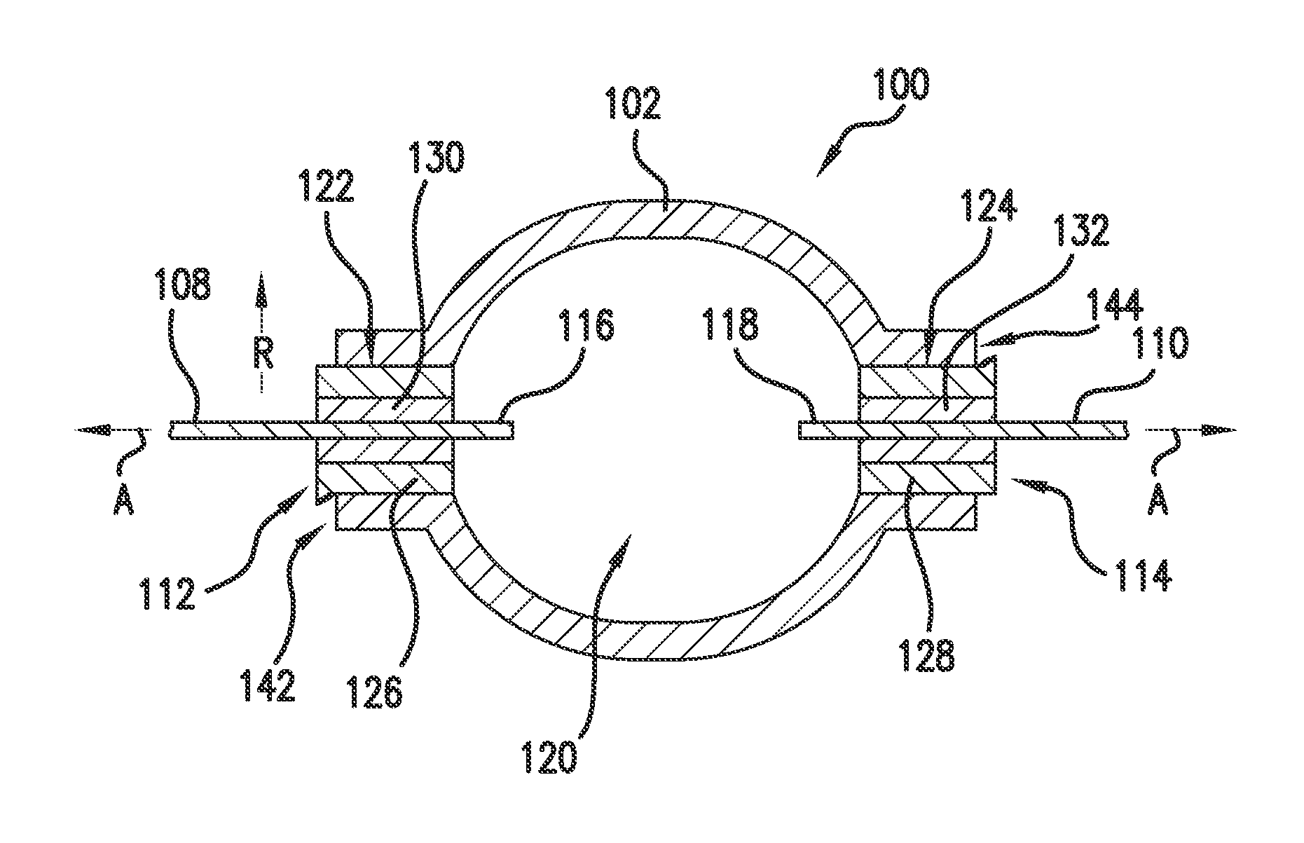
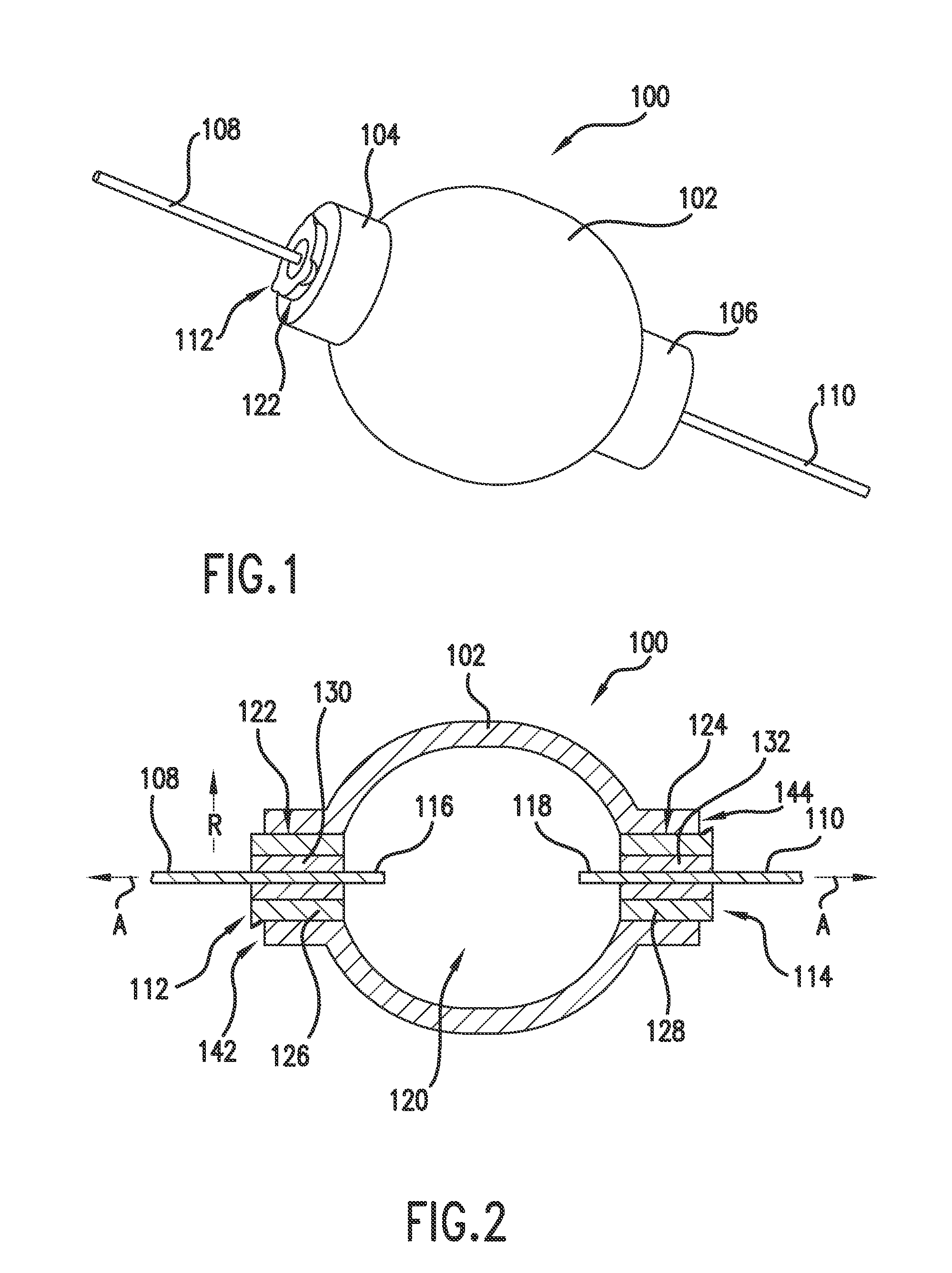
[0029]FIG. 1 illustrates a perspective view of an exemplary embodiment of a lamp 100 of the present invention while FIG. 2 provides a cross sectional view of lamp 100. Lamp 100 includes a body 102 defining a chamber 120 into which various materials have bee...


PUM


Abstract

A voidless CMH lamp and a method of making such a lamp are provided. The CMH lamp includes a lamp body that receives at least one end plug. The end plug is constructed from a core of cermet material received within an outer layer of a ceramic material. An electrode is placed into the cermet material. The application of heat causes the cermet material to contract and eliminate voids between the lamp and cermet material. Co-sintering of the lamp, core, and outer layer provides a hermetic seal without necessarily using e.g., a sealing frit. Sintering of the ceramic material surrounding the cermet can be also used to improve light output and photometric performance of the lamp. The creation of one or more openings or recesses in the end plug can also provide performance improvements.

Description

PRIORITY CLAIM[0001]This application claims the benefit of priority of U.S. Provisional Patent Application No. 61 / 700,006, filed Sep. 12, 2012, which is incorporated herein by reference for all purposes.FIELD OF THE INVENTION[0002]The subject matter of the present disclosure relates generally to voidless ceramic metal halide lamps.BACKGROUND OF THE INVENTION[0003]Ceramic metal halide (CMH) lamps (sometimes referred to as ceramic discharge metal halide lamps) generally include a tube or lamp body constructed of a ceramic material such as sintered alumina that forms a chamber into which a dose of e.g., mercury, argon, and halide salts are introduced. Electrodes are positioned at ends of the tube that, when energized, will cause the lamp to emit light. Depending upon the mixture of halide salts, the emitted light can closely resemble natural daylight. Additionally, for a comparable light output, CMH lamps can be operated with significantly less energy than a traditional, incandescent l...

Claims


Application Information

Patent Timeline
Patent Type & Authority Applications(United States)
IPC IPC(8): H01J9/26
CPCH01J9/26H01J61/363H01J9/247H01J9/266H01J9/32H01J9/323H01J9/395
Inventor RAMAIAH, RAGHURICHARDS, MILES ELLIOTTHOMPSON, DAVID ALLEN
Owner GENERAL ELECTRIC CO
Why Eureka
Try Eureka