
Switch for Clock Synchronization Over A Switched Fabric

a switch fabric and fabric technology, applied in multiplex communication, generating/distributing signals, instruments, etc., can solve the problems of difficult synchronization of device clocks to master time, difficult synchronization of devices in different fabric domains, etc., and achieve accurate time synchronization

Active Publication Date: 2014-03-13
NATIONAL INSTRUMENTS
View PDF1 Cites 77 Cited by
  • Summary
  • Abstract
  • Description
  • Claims
  • Application Information

AI Technical Summary

Benefits of technology

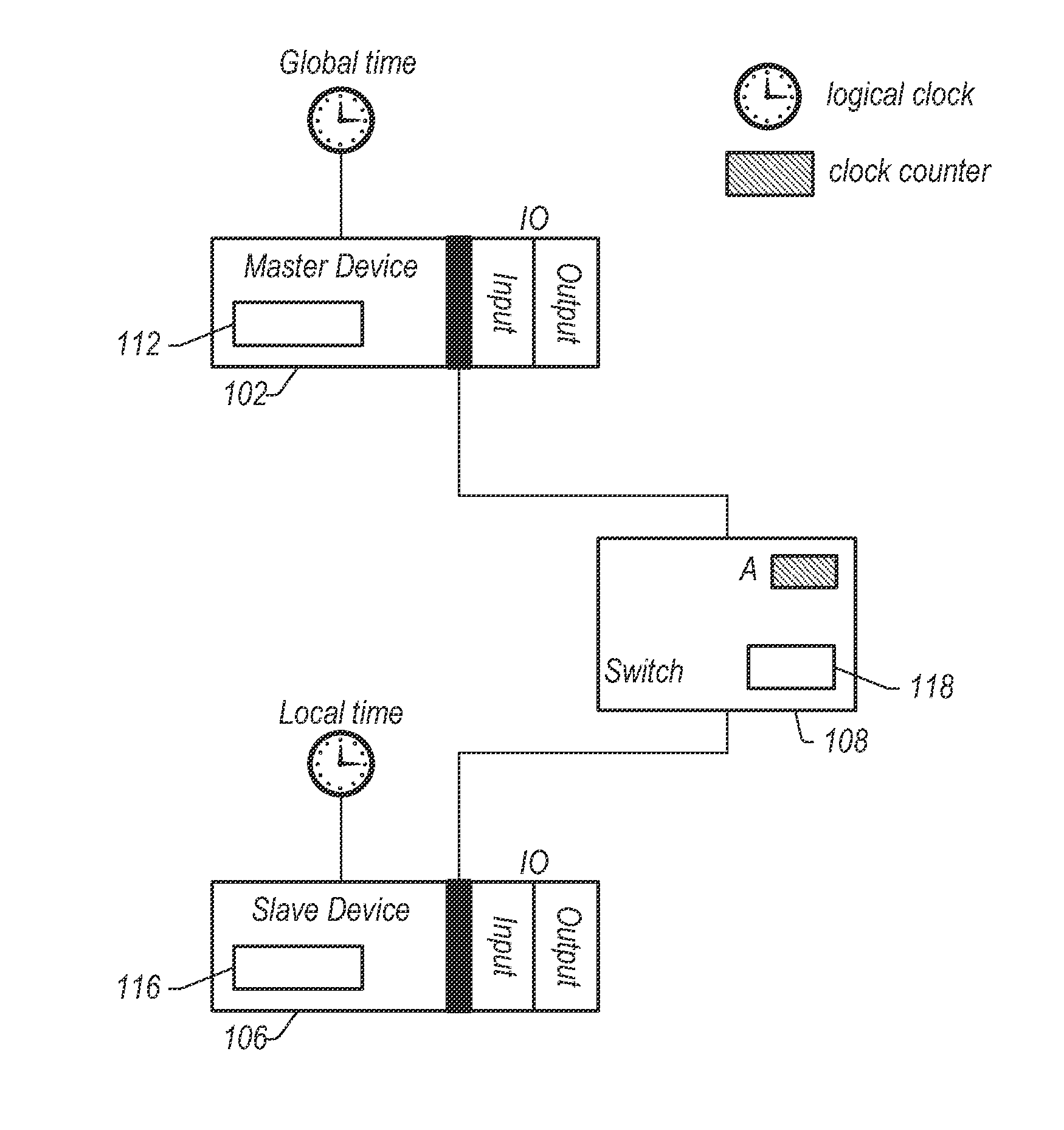
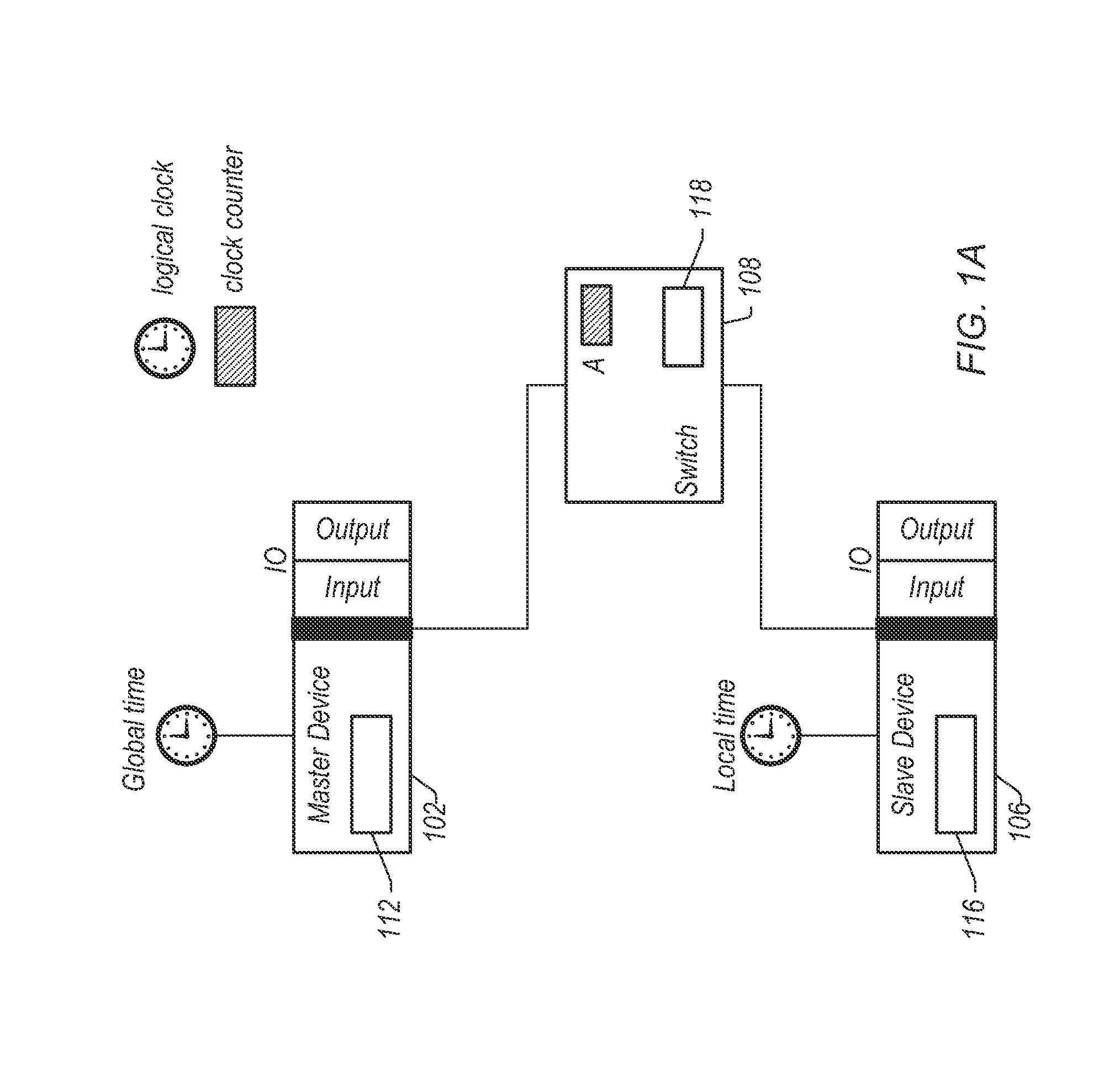
The patent is about switches and methods that can make it easier to synchronize the time between different devices that are connected using a switched fabric. This can be helpful when multiple clock domains or non-transparent bridges are involved.

Problems solved by technology

Synchronizing device clocks to a master time may be difficult over a switched fabric because of traffic congestion and buffering of transactions in switches.
Further, synchronization of devices in different fabric domains may be difficult.

Method used


Image

  • Switch for Clock Synchronization Over A Switched Fabric
  • Switch for Clock Synchronization Over A Switched Fabric
  • Switch for Clock Synchronization Over A Switched Fabric

Examples


Embodiment Construction

Terms

[0033]The following is a glossary of terms used in the present application:

[0034]Memory Medium—Any of various types of memory devices or storage devices. The term “memory medium” is intended to include an installation medium, e.g., a CD-ROM, floppy disks, or tape device; a computer system memory or random access memory such as DRAM, DDR RAM, SRAM, EDO RAM, Rambus RAM, etc.; or a non-volatile memory such as a magnetic media, e.g., a hard drive, or optical storage. The memory medium may comprise other types of memory as well, or combinations thereof. In addition, the memory medium may be located in a first computer in which the programs are executed, and / or may be located in a second different computer which connects to the first computer over a network, such as the Internet. In the latter instance, the second computer may provide program instructions to the first computer for execution. The term “memory medium” may include two or more memory mediums which may reside in different...


PUM


Abstract

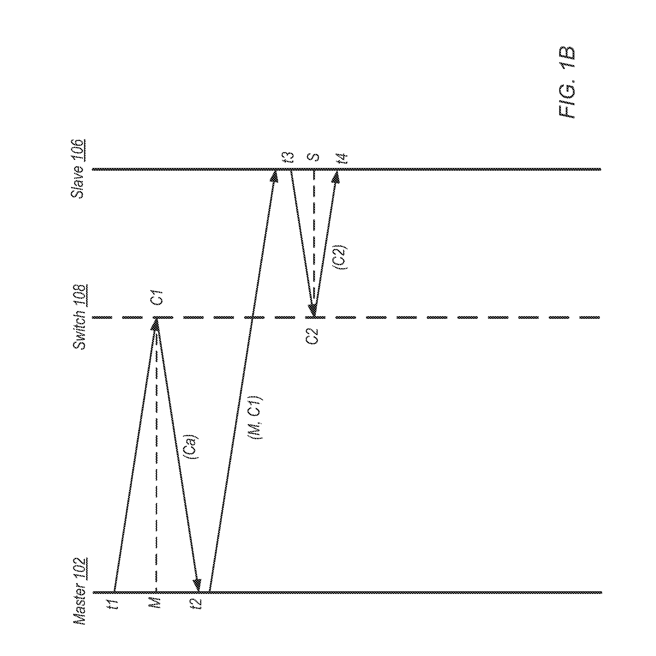
Devices and methods for synchronizing devices over a switched fabric. A switch receives a request packet from a device, transmits a completion packet to the device, determines an in-switch delay, and stores the in-switch delay. Another switch receives a packet from a first device, forwards the packet to a second device, determines an in-switch delay of the packet, and stores the in-switch delay. Storing of in-switch delays may include adding an in-switch delay to values in one or more transaction delay fields of a packet. Storing of in-switch delays may include storing the delays in a storage element of a switch. In-switch delay may be determined as a difference between a receiving time corresponding to reception of a packet and a forwarding or transmittal time corresponding to forwarding or transmitting of a packet.

Description

INCORPORATION BY REFERENCE[0001]The following references are hereby incorporated by reference in their entirety as though fully and completely set forth herein:[0002]U.S. Pat. No. 4,914,568 titled “Graphical System for Modeling a Process and Associated Method,” issued on Apr. 3, 1990.[0003]U.S. Pat. No. 5,481,741 titled “Method and Apparatus for Providing Attribute Nodes in a Graphical Data Flow Environment”.[0004]U.S. Pat. No. 6,173,438 titled “Embedded Graphical Programming System” filed Aug. 18, 1997.[0005]U.S. Pat. No. 6,219,628 titled “System and Method for Configuring an Instrument to Perform Measurement Functions Utilizing Conversion of Graphical Programs into Hardware Implementations,” filed Aug. 18, 1997.[0006]U.S. Pat. No. 7,210,117 titled “System and Method for Programmatically Generating a Graphical Program in Response to Program Information,” filed Dec. 20, 2000.FIELD OF THE INVENTION[0007]The present invention relates to the field of networked devices, and, more partic...

Claims


Application Information

Patent Timeline
Patent Type & Authority Applications(United States)
IPC IPC(8): G06F1/12
CPCG06F1/12G06F1/14H04J3/0673H04J3/0667G06F13/4022
Inventor CHANDHOKE, SUNDEEPGREENSTREET, RODNEY D.
Owner NATIONAL INSTRUMENTS
Learn More