Low Pressure Arc Plasma Immersion Coating Vapor Deposition and Ion Treatment

a technology of plasma immersion coating and vapor deposition, which is applied in the direction of vacuum evaporation coating, coating, electrolysis components, etc., can solve the problems of poor adhesion, poor structure and morphology, and low density of coatings

Active Publication Date: 2014-03-20
VAPOR TECH
View PDF6 Cites 33 Cited by
  • Summary
  • Abstract
  • Description
  • Claims
  • Application Information

AI Technical Summary

Benefits of technology

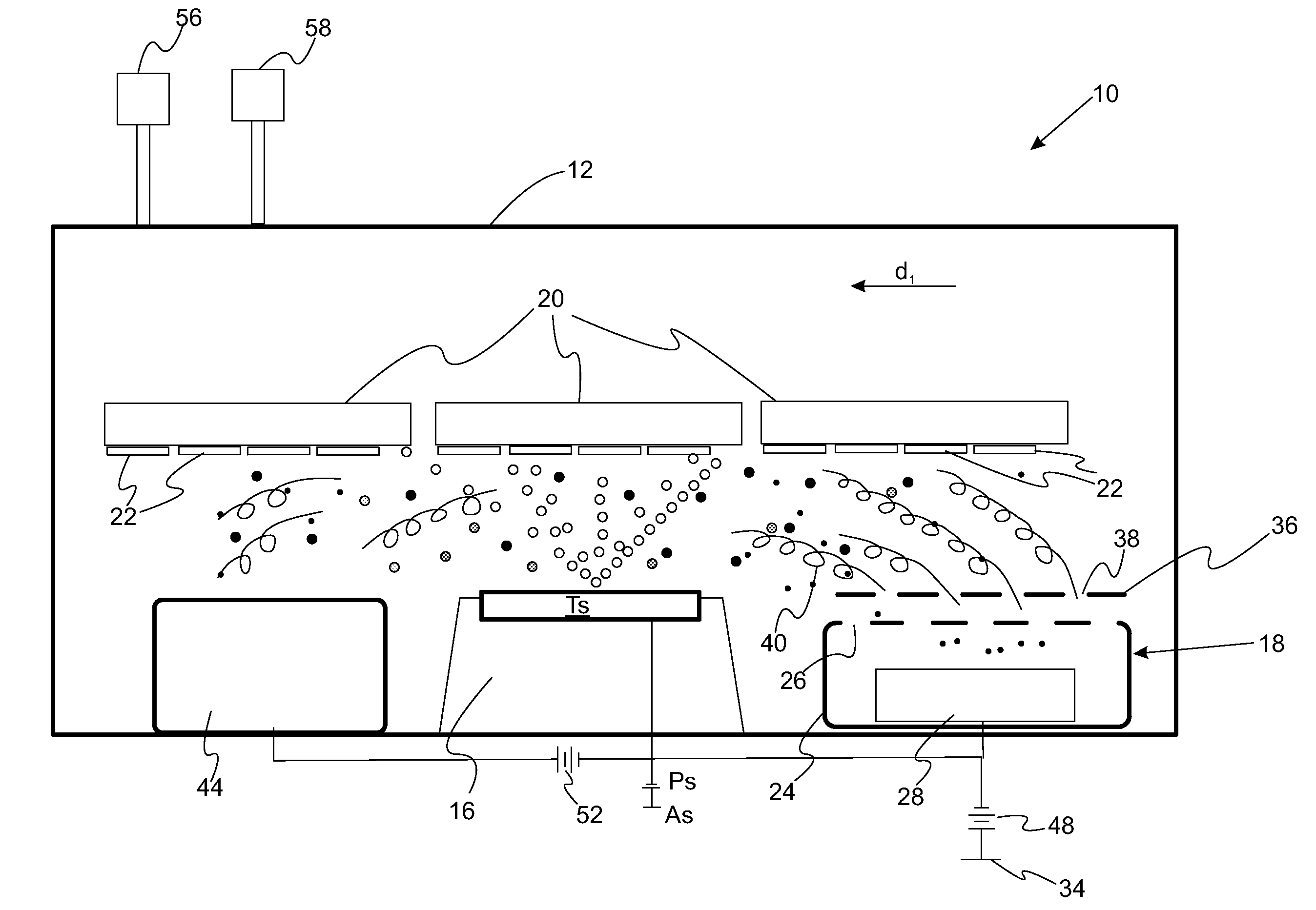
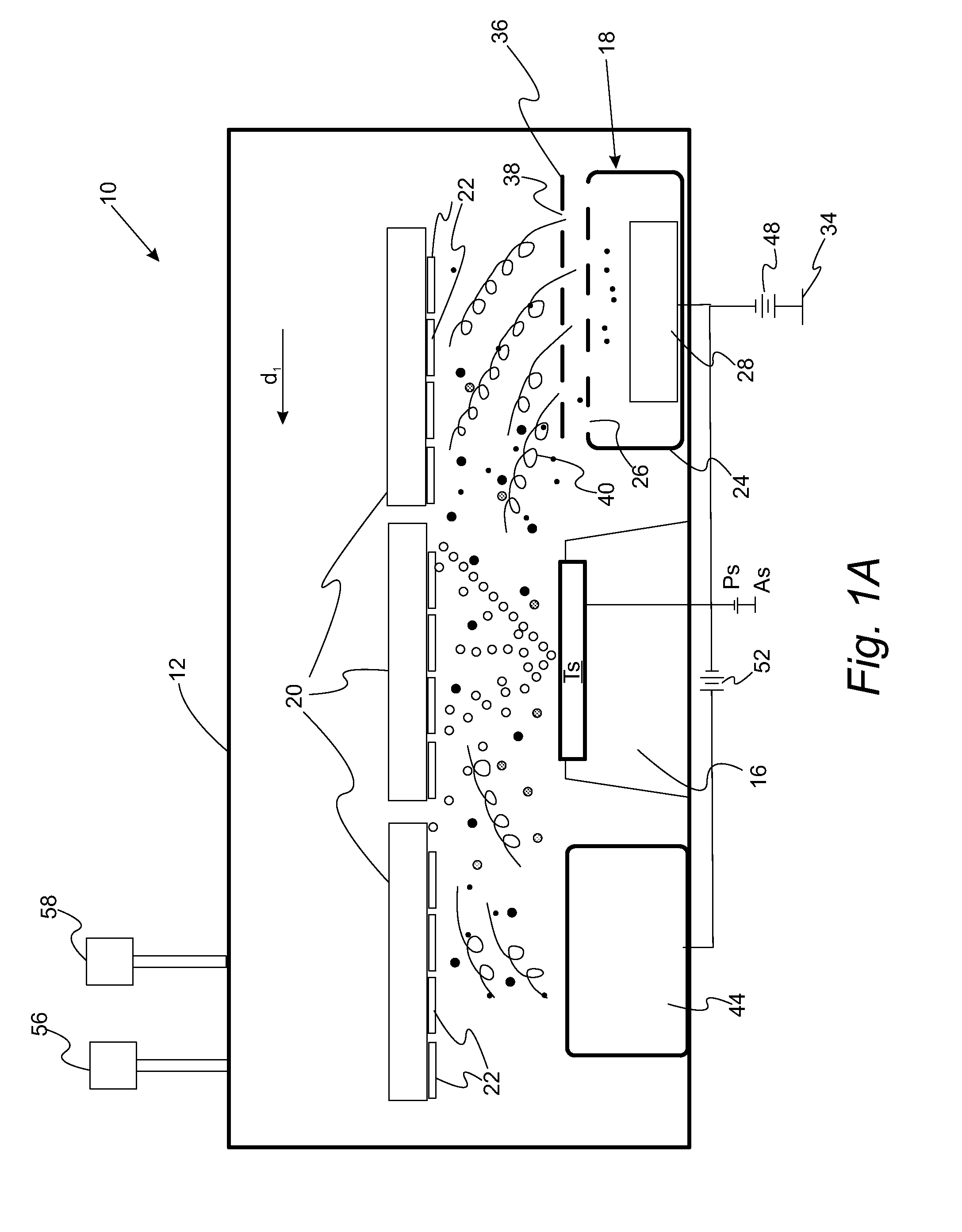
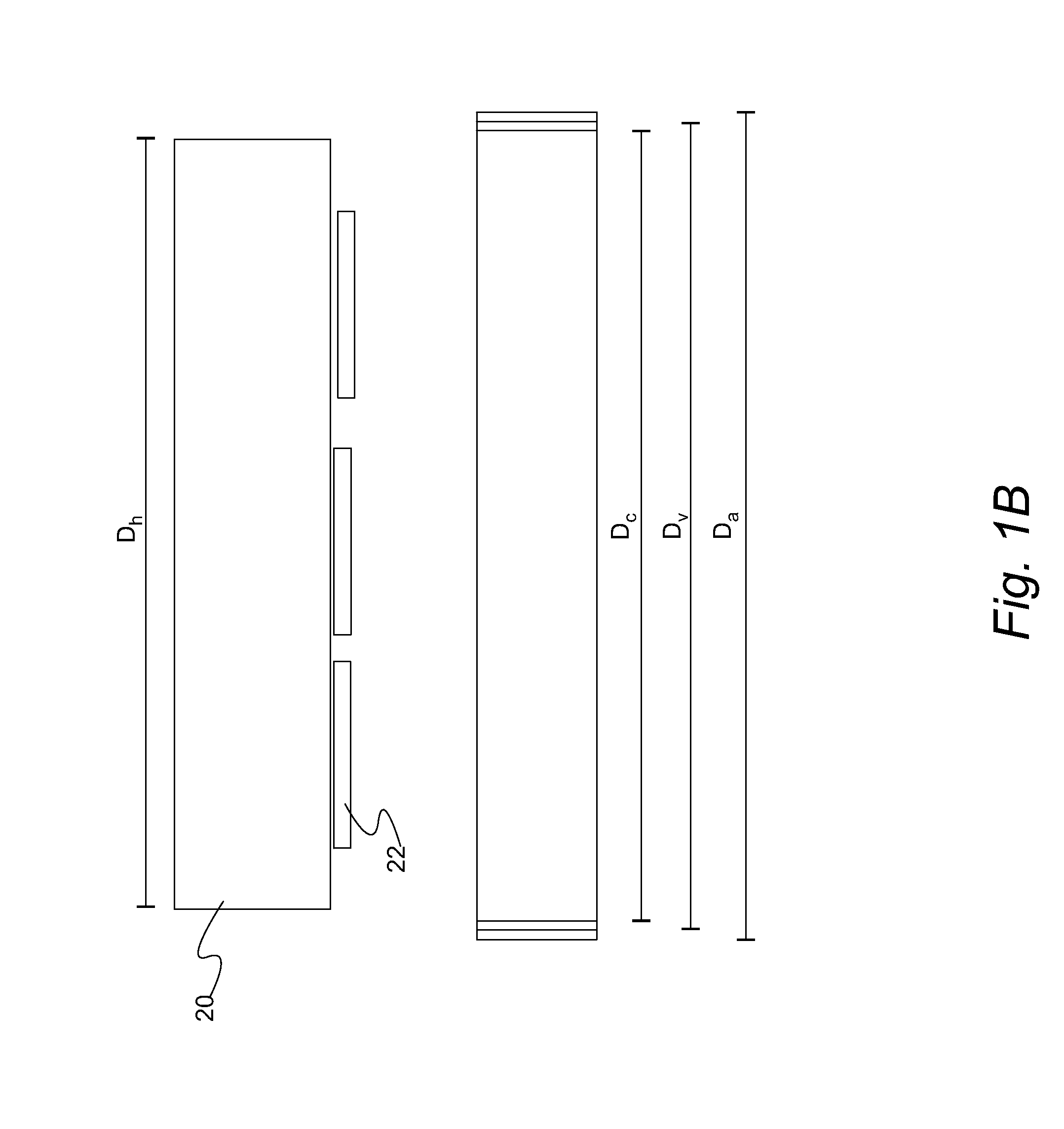
[0013]The present invention solves one or more problems of the prior art by providing in at least one embodiment a system for coating a substrate. The coating system includes a vacuum chamber and a coating assembly positioned within the vacuum chamber. The coating assembly includes a vapor source that provides material to be coated onto a substrate, a substrate holder to hold substrates to be coated such that the substrates are positioned in front of the vapor source, a cathode chamber assembly, and a remote anode. The cathode chamber assembly includes a cathode target, an optional primary anode and a shield which isolates the cathode from the vacuum chamber. The shield defines openings for transmitting an electron emission current from the cathode into the vacuum chamber. The vapor source is positioned between the cathode chamber assembly and the remote anode while the remote anode is electrically coupled to the cathode. The coating system also includes a primary power supply connected between the cathode target and the primary anode and a secondary power supply connected between the cathode target and the remote anode. Characteristically, the remote anode has a linear remote anode dimension, the vapor source has a linear vapor source dimension, the cathode target has a linear cathode target dimension, and the substrate holder has a linear holder dimension such that the linear remote anode dimension, the linear vapor source dimension, the linear cathode target dimension, and the linear holder dimension are parallel to each other, with the linear remote anode dimension being equal to or greater than the linear cathode target dimension and the linear vapor source dimension such that a confined plasma streams from the cathode target to the remote anode.

Problems solved by technology

However, the low energy of the metal vapor atoms and the low ionization rate of these processes result in coatings with low density, poor adhesion, poor structure and morphology.
Although the IBAD process works reasonably well, it has limitations due to its line-in-sight nature which is detrimental to achieving uniform coating distribution over complex shape components when the conformity of the coating deposition process is important.
In addition, the IBAD process has limited scale up capability.
Electron beam physical vapor deposition (EBPVD) technology, both conventional and ionized, has been used in many applications, but is generally not considered a viable manufacturing technology in many fields because of batch-processing issues, difficulties of scaling up to achieve uniform coating distribution across large substrates and because of the difficulty of multi-elemental coating composition control due to thermodynamically driven distillation of the elements with different vapor pressures.
Cathodic and anodic arc enhanced electron beam physical vapor deposition (EBPVD) processes dubbed hot evaporated cathode (HEC) and hot evaporated anode (HEA) respectively have demonstrated increased ionization rate, but suffer from arc spots instabilities and non-uniform distribution of the ionization rate across the EBPVD metal vapor flow.
In these processes, the arc discharge is coupled with evaporation process making it difficult to provide independent control of ionization and evaporation rates in HEA and HEC processes.
Therefore, it is extremely difficult to integrate PA-EBPVD processes in fully automated industrial batch coating systems.
These crystal structures may have undesired anisotropic properties specific for wear and cosmetic applications.
Since the pulse parameters are coupled with magnetron sputtering process parameters in the HIPIMS process, the sputtering rate, which is found to be almost three times lower than that of the conventional DC-MS process, can be adversely affected.
Moreover, the high voltage pulses in the HIPIMS process may induce arcing on magnetron targets resulting in contamination of the growing films.
A water cooled inductive coil placed between the magnetron target and substrates to be coated adversely affects the metal sputtering flow.
The MS setup is therefore much more complicated, expensive, and difficult to integrate into existing batch coating and in-line coating system.
These disadvantages are also true for the microwave assisted magnetron sputtering (MW-MS) process.
However, the RF, MW and ICP approaches to ionizing the PVD process experience difficulties with plasma distribution uniformity over a large processing area, which is an obstacle for integration into large area coating deposition systems.
However, this process typically exhibits plasma non-uniformity and is difficult to integrate in industrial large area coating systems.
Moreover, both hot filaments and hollow arc cathodes are sensitive and degrade quickly in the reactive plasma atmosphere.
The cosmetic appearance of the conventional cathodic arc deposited films includes particulates of un-reacted target material called macros that renders the deposited film with defects undesired in applications requiring specific wear, corrosion and cosmetic properties.
However, arc deposited films do not have a crystalline character unlike sputtered films because the arc evaporation process produces highly ionized plasma with a high energy of depositing atoms believed to effectively randomize crystal structures in the developing film.

Method used


Image

  • Low Pressure Arc Plasma Immersion Coating Vapor Deposition and Ion Treatment
  • Low Pressure Arc Plasma Immersion Coating Vapor Deposition and Ion Treatment
  • Low Pressure Arc Plasma Immersion Coating Vapor Deposition and Ion Treatment

Examples


Embodiment Construction

[0068]Reference will now be made in detail to presently preferred compositions, embodiments and methods of the present invention, which constitute the best modes of practicing the invention presently known to the inventors. The Figures are not necessarily to scale. However, it is to be understood that the disclosed embodiments are merely exemplary of the invention that may be embodied in various and alternative forms. Therefore, specific details disclosed herein are not to be interpreted as limiting, but merely as a representative basis for any aspect of the invention and / or as a representative basis for teaching one skilled in the art to variously employ the present invention.

[0069]Except in the examples, or where otherwise expressly indicated, all numerical quantities in this description indicating amounts of material or conditions of reaction and / or use are to be understood as modified by the word “about” in describing the broadest scope of the invention. Practice within the nume...


PUM

PropertyMeasurementUnit
thicknessaaaaaaaaaa
thicknessaaaaaaaaaa
bias potentialaaaaaaaaaa

Abstract

A coating system includes a vacuum chamber and a coating assembly. The coating assembly includes a vapor source, a substrate holder, a remote anode electrically coupled to the cathode target, and a cathode chamber assembly. The cathode chamber assembly includes a cathode target, an optional primary anode and a shield which isolates the cathode target from the vacuum chamber. The shield defines an opening for transmitting an electron emission current of a remote arc discharge from the cathode target to the remote anode that streams along the target face long dimension. A primary power supply is connected between the cathode target and the primary anode while a secondary power supply is connected between the cathode target and the remote anode. Characteristically, a linear remote anode dimension and a vapor source short dimension are parallel to a dimension in which an arc spot is steered along the cathode target.

Description

CROSS REFERENCE TO RELATED APPLICATIONS[0001]This application is a continuation-in-part of U.S. application Ser. No. 13 / 617,005 filed Sep. 14, 2012, the disclosure of which is incorporated in its entirety by reference herein.FIELD OF THE INVENTION[0002]The present invention relates to plasma assisted deposition systems and related methods.BACKGROUND OF THE INVENTION[0003]Physical vapor deposition (PVD) and low pressure Chemical vapor deposition (CVD) sources are used for deposition of coatings and surface treatment. Conventional metal vapor sources such as electron beam physical vapor deposition (EBPVD) and magnetron sputtering (MS) metal vapor sources can provide high deposition rates. However, the low energy of the metal vapor atoms and the low ionization rate of these processes result in coatings with low density, poor adhesion, poor structure and morphology. It is well established that assistance of the coating deposition process with bombardment by energetic particles dramatica...

Claims


Application Information

Patent Timeline
Patent Type & Authority Applications(United States)
IPC IPC(8): C23C14/35
CPCC23C14/35C23C14/355H01J37/32055H01J37/32357H01J37/34H01J37/3405H01J37/3417H01J37/3438C23C14/32C23C14/325
Inventor GOROKHOVSKY, VLADIMIRGRANT, WILLIAMTAYLOR, EDWARDHUMENIK, DAVID
Owner VAPOR TECH
Why Eureka
Try Eureka