Co2 globular transfer

a globular transfer and co2 technology, applied in the direction of manufacturing tools, welding/cutting media/materials, welding apparatus, etc., can solve the problems of unstable globular transfer gmaw process, more splatter, slow arc welding process, etc., to achieve easy control, reduce output, and increase output

Active Publication Date: 2014-03-20
LINCOLN GLOBAL INC
View PDF23 Cites 20 Cited by
  • Summary
  • Abstract
  • Description
  • Claims
  • Application Information

AI Technical Summary

Benefits of technology

The patent describes a method for controlling the transfer of droplets during a welding process. By using pulses of power, the method reduces the force of the arc on the droplet, promoting a short circuit and allowing the droplet to touch the puddle more easily. This improves the quality of the weld and reduces the likelihood of defects. The method also uses a short clearing routine to detach the droplet from the puddle, ensuring a stable transfer. Overall, the method provides a more efficient and effective way to weld materials using advanced techniques.

Problems solved by technology

The patent text discusses the problem of instability and splatter during globular transfer GMAW welding processes. The technical problem is to find an improved welding technique to address these issues.

Method used


Image

  • Co2 globular transfer
  • Co2 globular transfer
  • Co2 globular transfer

Examples


Embodiment Construction

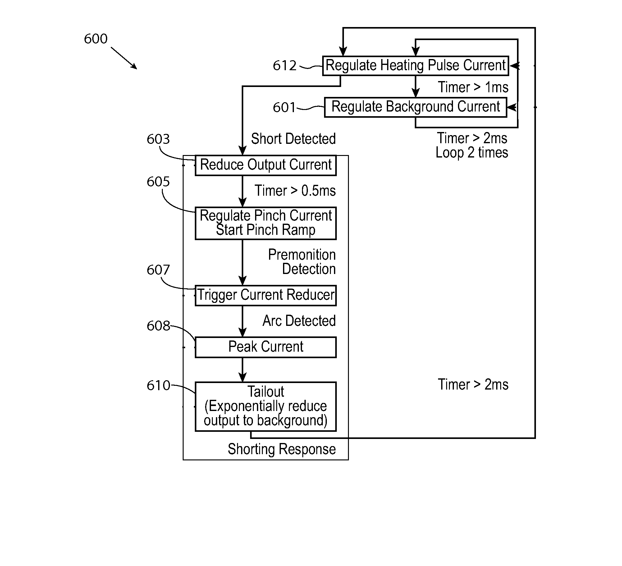
[0027]Embodiments of the invention relate to methods and systems that generally relate to generating a negative polarity welding output current waveform to control a welding process. An electric arc welding system generates an electric welding waveform with portions in a negative polarity. A cycle of the electric welding waveform includes a background current phase, a short clearing ramp phase after the background current phase, a peak current phase, and a tail-out current phase of the electric welding waveform, wherein the peak current phase provides a negative peak current level, the tail-out current phase provides a monotonically increasing tail-out current level toward the positive background current level, and the short clearing ramp phase provides a decreasing current level in a positive polarity of current for the electric welding waveform.

[0028]The best mode for carrying out the invention will now be described for the purposes of illustrating the best mode known to the appli...


PUM

PropertyMeasurementUnit
Polarityaaaaaaaaaa
Currentaaaaaaaaaa
Levelaaaaaaaaaa

Abstract

The invention described herein generally pertains to a system and method for generating a negative polarity welding output current waveform to control a welding process. An electric arc welding system generates an electric welding waveform with portions in a negative polarity. A cycle of the electric welding waveform includes a background current phase, a short clearing ramp phase after the background current phase, a peak current phase, and a tail-out current phase of the electric welding waveform, wherein the peak current phase provides a negative peak current level, the tail-out current phase provides a monotonically increasing tail-out current level toward the positive background current level, and the short clearing ramp phase provides a decreasing current level in a positive polarity of current for the electric welding waveform.

Description


Claims


Application Information

Patent Timeline
Owner LINCOLN GLOBAL INC
Why Eureka
Try Eureka