Vertical axis wind turbine with cambered airfoil blades

a vertical axis, wind turbine technology, applied in the direction of electric generator control, renewable energy generation, greenhouse gas reduction, etc., can solve the problems of increasing the complexity of the design, increasing manufacturing and maintenance costs, and affecting the efficiency of wind turbines, so as to reduce the friction of wind turbines and reduce interference with radar signals.

Active Publication Date: 2014-03-20
EPSTEIN MARTIN +3
View PDF8 Cites 24 Cited by
  • Summary
  • Abstract
  • Description
  • Claims
  • Application Information

AI Technical Summary

Benefits of technology

[0015]The novel wind turbine has blades that rotate in a horizontal plane about a vertical axis. A single output shaft is directly connected by one-way bearings to the driven shaft of a permanent magnet generator so that no gearbox is required and the elimination of the gearbox greatly reduces the friction losses of the system. Friction losses are further reduced by suspending the vertical axis of all rotating components with custom-designed magnetic bearings. Airfoils are positioned in a specific vertical design so that they cup the wind on a lower concave portion of the airfoil for self-starting capability. Stealth radar-absorbing mesh and faceted mounting structures reduce scrambling of radar returns.

Problems solved by technology

Conventional HAWTs have a number of serious flaws.
This increases the complexity of the design, which results in higher manufacturing and maintenance costs and a higher risk of failure.
The presence of a gearbox introduces additional frictional forces into the structure that reduce the power produced by the generator and also requires inverters between the generator and the power grid.
Conventional blades also have little self-start capacity.
Moreover, the large cantilevered design puts strong force moments on bearings with resultant energy loss and noise.
Large forces are created by such conventional designs, and large forces lead to high maintenance and high overhead costs.
The large surface area of conventional blades creates problems in high wind conditions, creating even more maintenance issues.
Furthermore, the complexity of HAWT designs requires a large number of moving parts, therefore increasing the risk of mechanical failure.
High fabrication cost, high assembly cost, and high maintenance cost increase the price of the energy produced, making wind energy a less lucrative option.
Long continuously rotating blades constantly ping radars and cause problems with radar coverage, which may be especially problematic for turbines positioned in open waters where vessels and aircraft heavily rely on radars.
Although a number of VAWT designs are known in the art, they are also flawed.
These advantages, however, come at a steep price of greatly reduced efficiency.

Method used


Image

  • Vertical axis wind turbine with cambered airfoil blades
  • Vertical axis wind turbine with cambered airfoil blades
  • Vertical axis wind turbine with cambered airfoil blades

Examples


Embodiment Construction

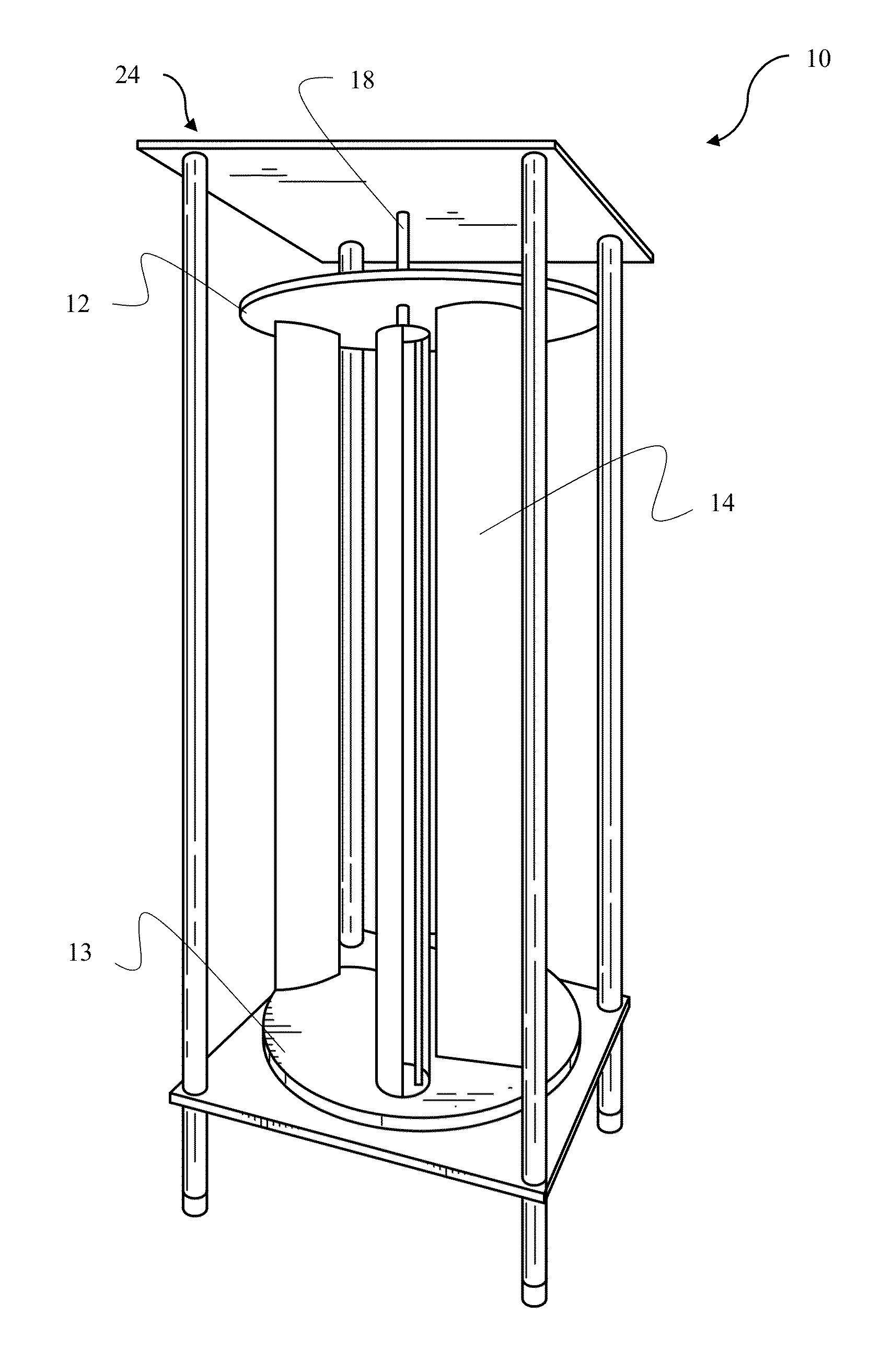
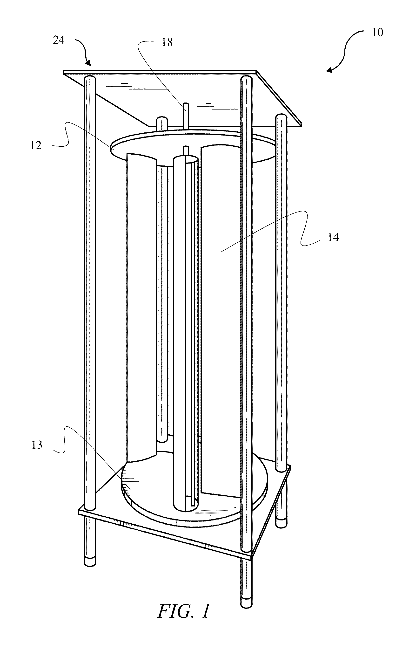
[0040]FIG. 1 depicts an illustrative embodiment of the novel structure which is denoted as a whole by the reference numeral 10.

[0041]The novel vertical axis wind turbine (VAWT) 10 is depicted in FIG. 1. VAWT 10 includes a top plate 12 and a bottom plate 13. A plurality of blades 14 is disposed between top and bottom plates 12 and 14. Blades 14 are symmetrically positioned about a center axis 17 of bottom plates 12 and 13. A vertical shaft 18 is in axial alignment with center axis 17 and is attached to bottom plate 13. In an embodiment, vertical shaft 18 may extend up to or beyond top plate 12 providing additional structural support without notable effect on aerodynamic profile of VAWT 10.

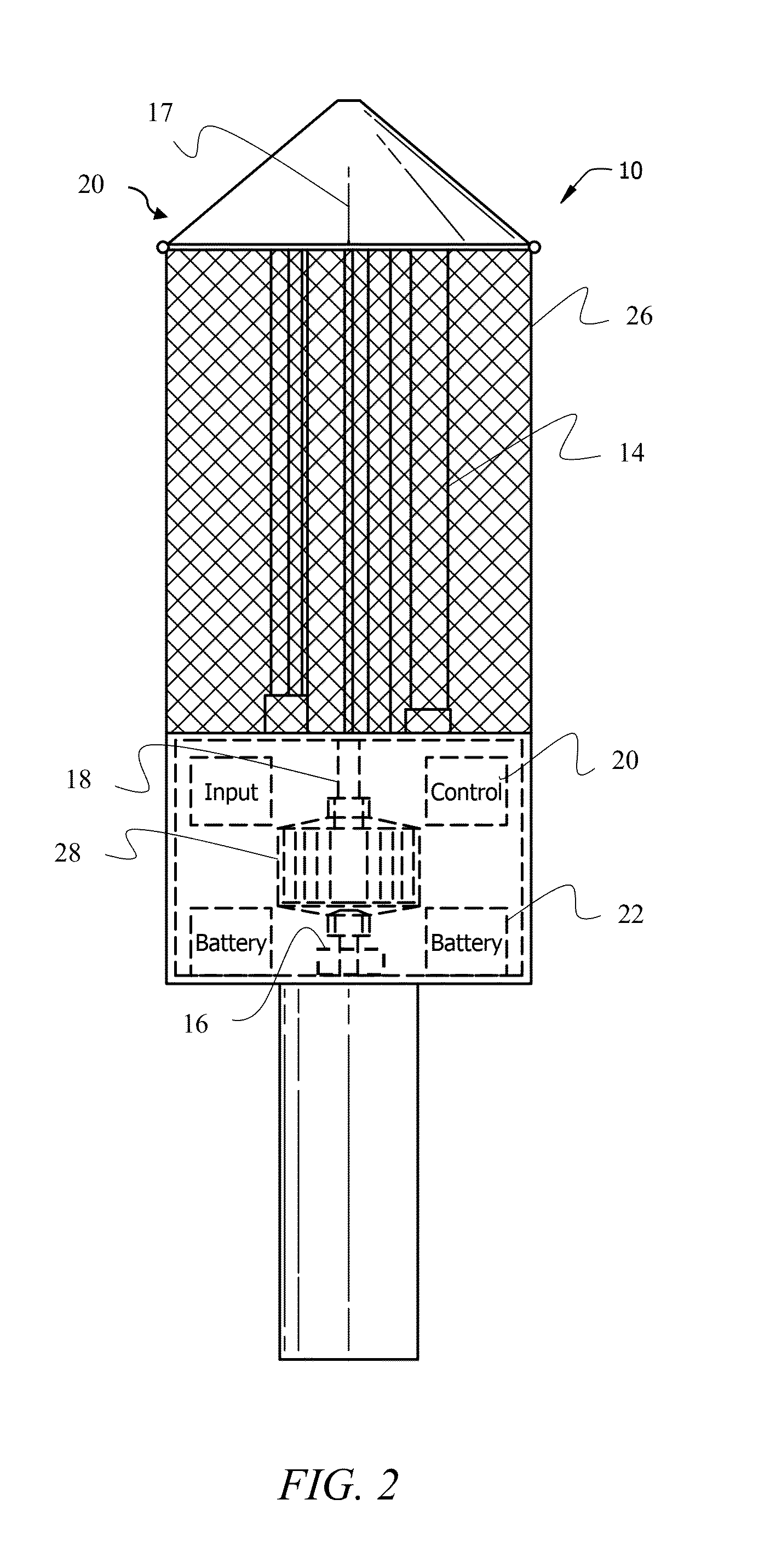
[0042]Referring to FIG. 2, vertical shaft 18 is supported by a magnetic bearing 16. Magnetic bearing 16 significantly reduces frictional losses, and therefore, improves overall efficiency of VAWT 10. Magnetic bearing 16 may be a passive magnetic bearing utilizing permanent magnets or an active magne...


PUM


Abstract

A wind turbine having blades that rotate in a horizontal plane about a vertical axis. A single output shaft is directly connected by one-way bearings to the driven shaft of a permanent magnet generator. This eliminates the need for a gearbox and also eliminates the need for inverters. Friction losses are further reduced by suspending the vertical shaft with magnetic bearings. Airfoils are positioned in a specific vertical design so that they cup the wind on a lower concave portion of the airfoil for self-starting capability. Stealth radar-absorbing mesh and faceted mounting structures reduce scrambling of radar returns.

Description

CROSS REFERENCE TO RELATED APPLICATION[0001]This application claims priority to currently pending U.S. Prov. Pat. Appl. No. 61 / 700,562, entitled “VERTICAL WIND TURBINE FOR CONTINUOUS POWER PRODUCTION,” filed on Sep. 13, 2012, the contents of which are hereby incorporated by reference.BACKGROUND OF THE INVENTION[0002]1. Field of the Invention[0003]This invention relates, generally, to wind turbines. More particularly, it relates to a high-efficiency vertical wind turbine.[0004]2. Description of the Prior Art[0005]As the cost of fossil fuels rises and their harmful effects on the environment come to forefront of global attention, alternative sources of energy grow in importance. One source of clean sustainable energy is wind. Humans have been harvesting the power of the wind for numerous applications for millennia. In the recent decades, wind turbines have become a significant source of electricity for many areas, and they are quickly becoming more widespread.[0006]All wind turbines m...

Claims


Application Information

Patent Timeline
Patent Type & Authority Applications(United States)
IPC IPC(8): F03D3/00F03D9/00
CPCF03D9/002F03D3/005F05B2240/95Y02E10/74F03D15/20F03D80/70F03D9/25Y02E10/727F03D3/062
Inventor EPSTEIN, MARTINHARMS, JON ERICSTINSON, WILLIAMESPOSITO, CLAUDIO
Owner EPSTEIN MARTIN
Why Eureka
Try Eureka