
System and method for electric vehicle (EV) charging

a charging system and electric vehicle technology, applied in the field of electric cars, can solve the problems of increasing the difficulty of charging even a single ev, and increasing the difficulty of practical realities, so as to reduce or eliminate the possibility of overloading the current source. , the effect of high strength materials

Inactive Publication Date: 2014-03-20
SPANOS MIKE
View PDF1 Cites 11 Cited by
  • Summary
  • Abstract
  • Description
  • Claims
  • Application Information

AI Technical Summary

Benefits of technology

This patent is about monitoring the use of current from a power source by multiple devices, including a charging unit for electric vehicles. The current is adjusted to prevent overloading the power source and any related circuits. The system includes high strength materials to prevent damage, a sealed system for fluid resistance, and redundant communication to ensure proper data feed. These technical measures provide safety and efficacy in the use of current for charging electric vehicles.

Problems solved by technology

When purchasing an EV, one of the practical challenges that meets the new owner is the seemingly obvious requirement that they will need ready access to a reliable source of electricity at their home in order to keep the battery for their EV charged and ready to go.
While the concept of plugging the EV into an electrical outlet is, on its face, a straightforward proposition, the practical realities are somewhat more challenging.
Additionally, the typical EVSE unit with a fixed current load may become a more problematic issue with older residences that have lower rated service panels (e.g., rated at or below 100 amperes).
In these situations, charging even a single EV can be impossible due to the load restrictions for the residence and may require the costly installation of a second meter or require an upgrade to the main power supply panel of the residence.
Given the significant electrical demands for charging the batteries in electric vehicles, and the inadequate infrastructure found in many homes today, it is possible a significant number of homes will be unable to support the load associated with charging the EV battery.

Method used


Image

  • System and method for electric vehicle (EV) charging
  • System and method for electric vehicle (EV) charging
  • System and method for electric vehicle (EV) charging

Examples


Embodiment Construction

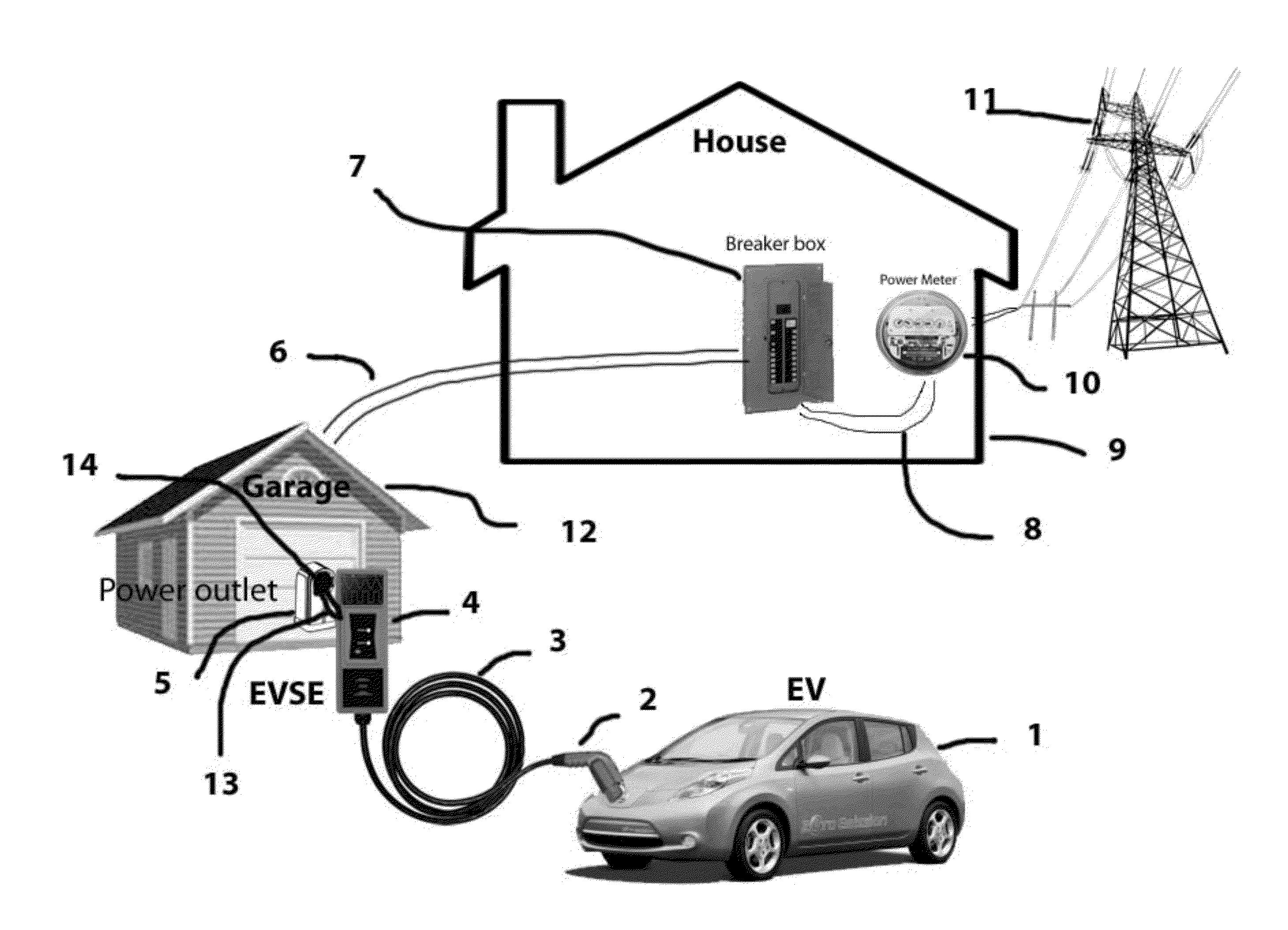
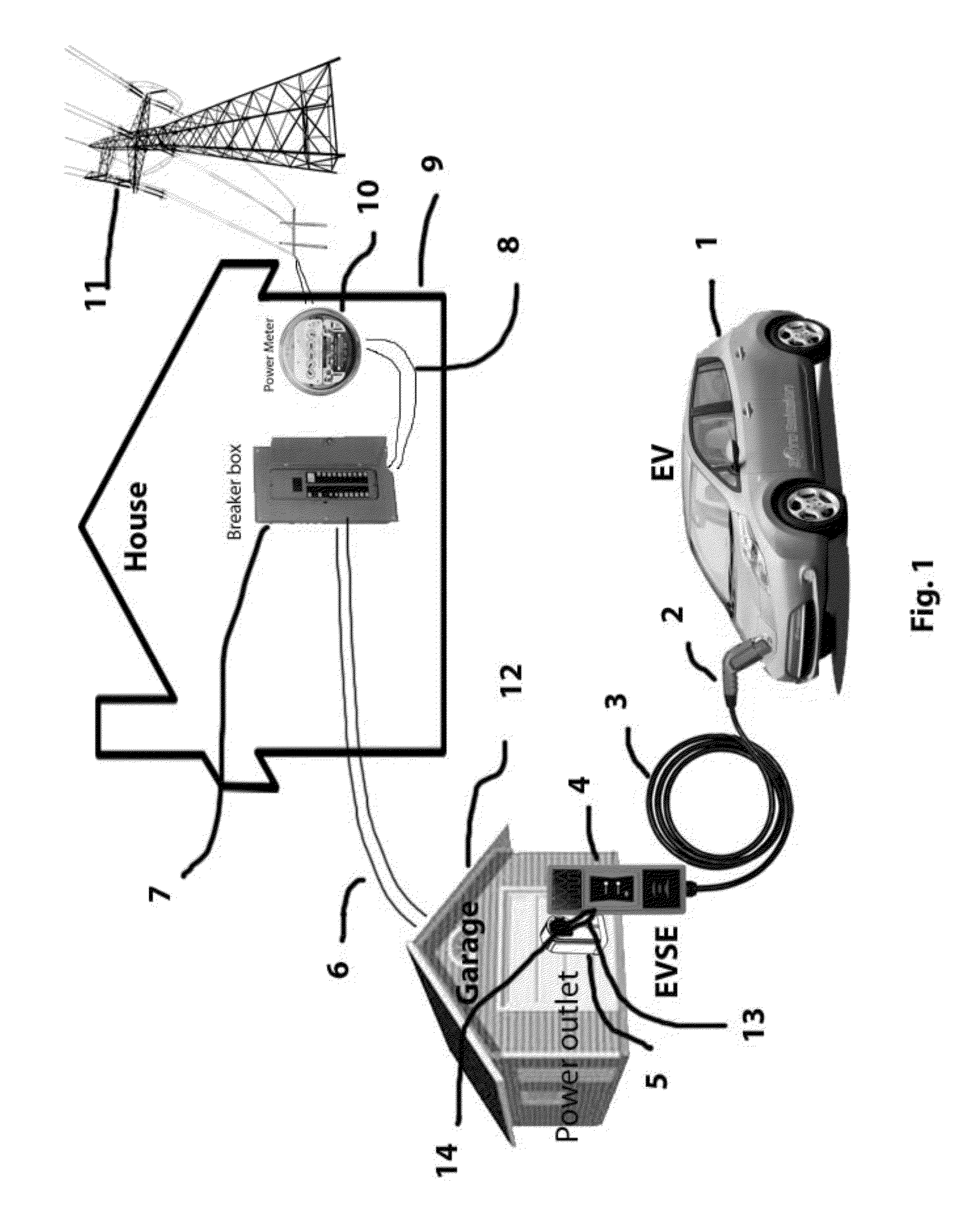
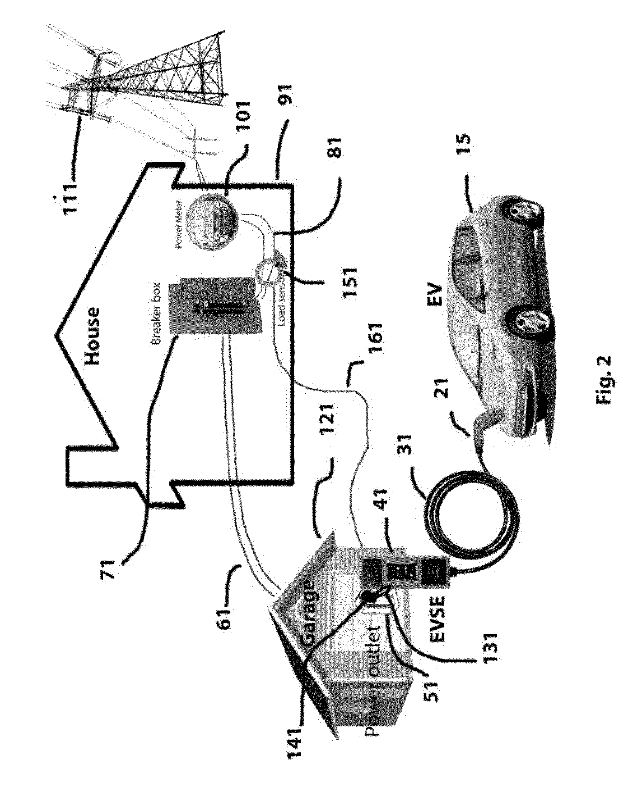
[0019]In contrast to the presently known EVSE charging systems, the various preferred embodiments of the EVSE of the present invention are connected to the residence power system via a wall outlet and is still considered an appliance by the power company and it is determined with the max load is for the system based on load calculations of the residence other appliances and max power at the box and this max draw is input into the EVSE computer system as the FAIL safe max load. Then the EVSE sensor is connected to the main power line servicing the electrical panel for the residence and it determines the load the residence in real time. For example if you have a 200 amp panel and you have an AC unit drawing 25 amps, a refrigerator drawing 15 amps, a TV drawing 5 amps and lights drawing 5 amps your system is drawing 50 amps the Calculation for the safe load for a dumb unit will only allow the unit to Draw 20 amps period so you are using 70 amps but you have 200 amps available. The smar...


PUM


Abstract

A smart Electric Vehicle Supply Equipment (“EVSE”) that will accept input from different sources to determine the max rate of charge an Electric Vehicle (EV) can be safely charged at without overloading the electrical system of the residence. The system will also communication signals from the power company, fire department and police to reduce or eliminate the charging of the battery in the EV if the situation requires. The smart EVSE further comprises a non-invasive current and / or load sensing unit coupled to the power source for recharging the battery or batteries in the EV, cables to connect the load sensing unit to the EVSE, and optional wireless communication transmitter (sensor to EVSE), EVSE unit with compensating ability.

Description

CROSS REFERENCE TO RELATED APPLICATIONS[0001]This application claims the benefit of U.S. Provisional Patent Application No. 61 / 537,395, filed on Sep. 20, 2011, the contents of which are incorporated herein by reference, as if fully set forth herein.BACKGROUND OF THE INVENTION[0002]1. Field of the Invention[0003]The present invention relates generally to the field of electric cars and more specifically relates to charging systems for electric cars.[0004]2. Related Art[0005]Electric cars or electric vehicles (“EVs”) are becoming increasingly prevalent throughout the world, and especially so in the United States of America. The growth of electric cars is tied to many factors, including a growing awareness of environmental issues, reductions in the price of the technology, and a desire to decrease the dependence on fossil fuels for the overall economy. Taken together, these factors, as well as many others, has driven automobile manufacturers to rapidly adopt and deploy electric vehicles...

Claims


Application Information

Patent Timeline
Patent Type & Authority Applications(United States)
IPC IPC(8): B60L11/18
CPCB60L11/1824B60L53/14B60L53/305Y02T10/70Y02T10/7072Y02T90/12Y02T90/14Y02T90/16B60L53/30
Inventor SPANOS, MIKE
Owner SPANOS MIKE
Learn More