
Method for generating an array of 3-d points

a technology of point array and array, applied in the field of generating an array of 3d points, can solve the problems of difficult to near impossible to generate a surface from such a point set, prohibitively expensive laser scanner systems, and substantial time required to process three-dimensional objects, and achieve the effect of inexpensively and reliably gen

Active Publication Date: 2014-03-20
BROWN UNIVERSITY
View PDF33 Cites 44 Cited by
  • Summary
  • Abstract
  • Description
  • Claims
  • Application Information

AI Technical Summary

Benefits of technology

The present invention is about a method and system for creating a complete and accurate set of 3-D points from a photograph. This invention provides a cost-effective and reliable solution for generating 3-D points that can be used for feature matching relative to a database of known surfaces.

Problems solved by technology

The difficulty, however, is that laser scanner systems are prohibitively expensive and require substantial time to process a three dimensional object.
This makes it difficult to near impossible to generate a surface from such a point set.
However, the calibration procedure must be adapted to the fact that projectors cannot directly measure the pixel coordinates of 3D points projected onto the projector image plane as cameras do.
Many projector calibration procedures exist, however, none of the available methods are easy for the common user to perform.
Further, they generally require high precision to enable accurate 3D reconstructions.
These methods might be simple to perform, but all of them lack of accuracy in the projector parameters due to their dependence on the camera calibration.
The inaccuracies are a direct consequence of their approach: even small camera calibration errors could result into large world coordinate errors.
Their failure point is in estimating the projector parameters from the, far from accurate, world coordinates decreasing the complete system precision.
However, moving the projector is generally inconvenient or impossible (e.g. a system mounted on a rig).
Moreover, these methods are not applicable if a metric reconstruction is mandatory because their result is only up-to-scale.
In practice, switching to color patterns makes color calibration unavoidable as printed and camera colors seldom match, thereby imposing an extra requirement to the user.
Despite the elegance of the concept, they cannot model non-linear distortions as the ones introduced by projector lenses.
However, such a special equipment is not available to the common user, limiting its general applicability.
We disregard this method as non-practical.

Method used


Image

  • Method for generating an array of 3-d points
  • Method for generating an array of 3-d points
  • Method for generating an array of 3-d points

Examples


Embodiment Construction

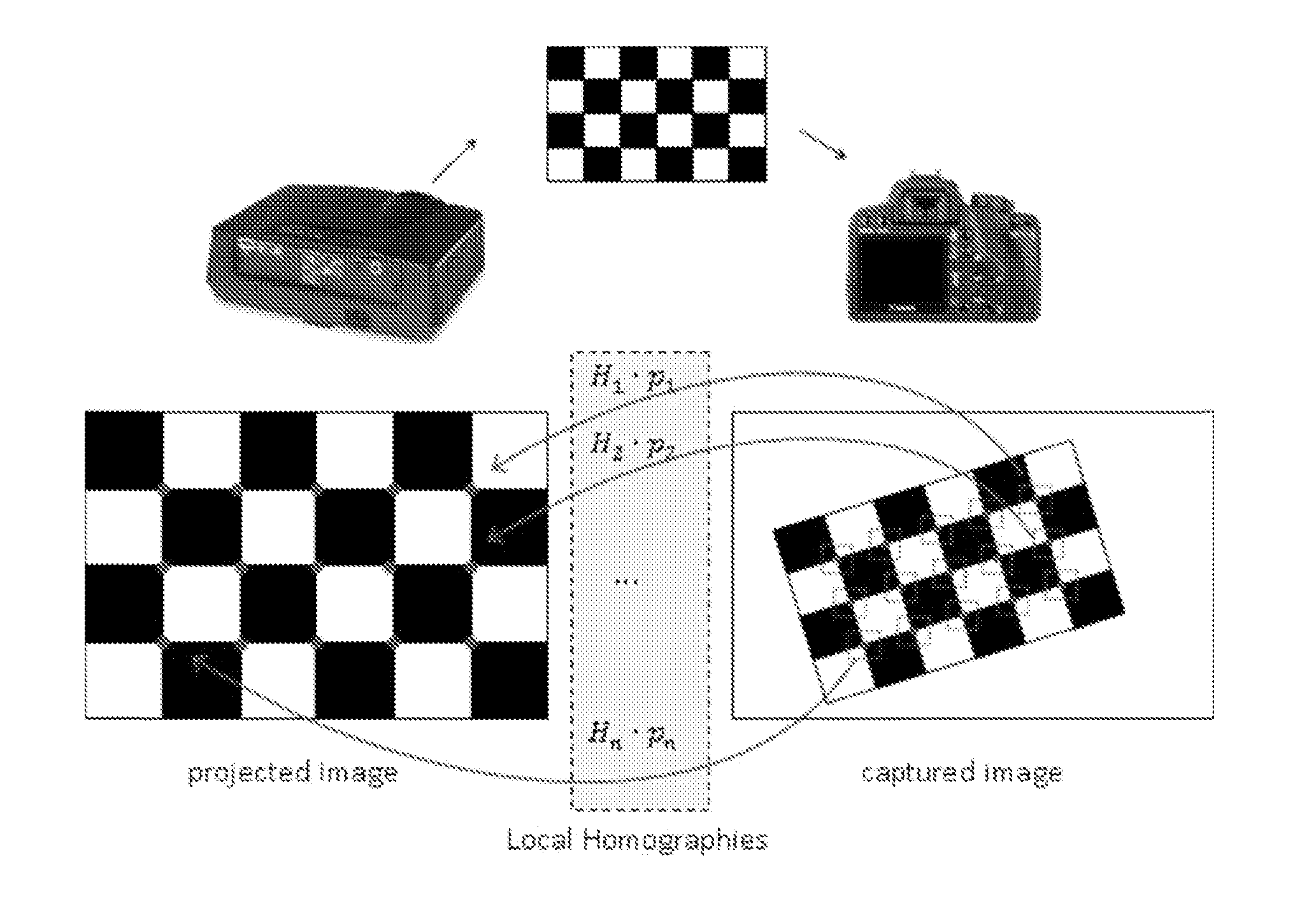
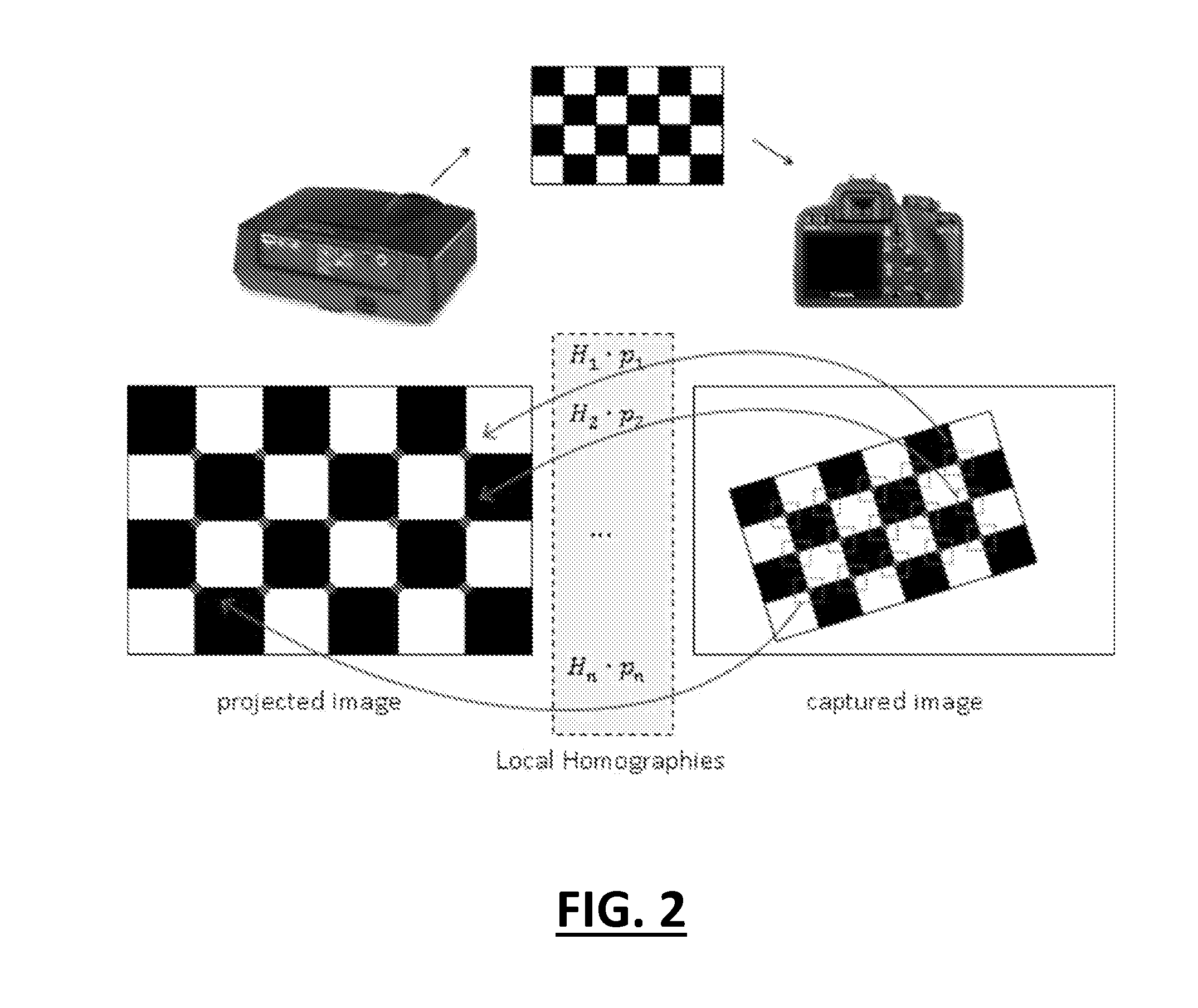
[0025]The present invention provides generally for a method that estimates the coordinates of the calibration points in the projector image plane using local homographies obtained from the imaging camera. First, a dense set of correspondences between projector and camera pixels is found by projecting onto the calibration object an identical pattern sequence as the one later projected when scanning the target, reusing most of the software components written for the scanning application. Second, the set of correspondences is used to compute a group of local homographies that allow projection back of any of the points in the calibration object onto the projector image plane with sub-pixel precision. In the end, the data projector is then calibrated as a normal camera.

[0026]Principally the present method focuses on finding correspondences between the projector pixels and real 3D world points. Once those correspondences are known, any calibration technique available for passive stereo ca...


PUM


Abstract

A method that estimates the coordinates of the calibration points in the projector image plane using local homographies obtained from the imaging camera. First, a dense set of correspondences between projector and camera pixels is found by projecting onto the calibration object an identical pattern sequence as the one later projected when scanning the target, reusing most of the software components written for the scanning application. Second, the set of correspondences is used to compute a group of local homographies that allow projection back of any of the points in the calibration object onto the projector image plane with sub-pixel precision. In the end, the data projector is then calibrated as a normal camera.

Description

CROSS-REFERENCE TO RELATED APPLICATIONS[0001]This application is related to and claims priority from earlier filed U.S. Provisional Patent Application No. 61 / 703,520, filed Sep. 20, 2012.GOVERNMENT FUNDING[0002]The subject matter of this application was funded in part by NSF Grants IIS-0808718 and CCF-0915661.BACKGROUND OF THE INVENTION[0003]The present invention relates generally to computer implemented system and algorithm for generating a surface from an array of points that have been captured from photographs. More specifically, the present invention relates to a system that generates a highly accurate array of points that can then be used as an effective and accurate tool for surface feature generation and matching in a wide range of applications.[0004]It is well known in the art that there are many tools available for digitizing a three dimensional surface profile. Laser scanner systems, for example, can generate highly accurate surface measurements and 3-D models. The difficu...

Claims


Application Information

Patent Timeline
Patent Type & Authority Applications(United States)
IPC IPC(8): H04N13/02
CPCH04N13/0246G06T2207/30244G06T7/85G06T7/521G06T7/80H04N13/246
Inventor TAUBIN, GABRIELMORENO, DANIEL
Owner BROWN UNIVERSITY
Learn More