
Microelectromechanical system (MEMS) and (MEM) optical interferometer for hyper-spectral imaging and analysis

a microelectromechanical system and optical interferometer technology, applied in the field of hyperspectral imaging and analysis, can solve problems such as limited application of exemplary embodiments

Inactive Publication Date: 2014-03-20
GREENVISION SYST
View PDF2 Cites 6 Cited by
  • Summary
  • Abstract
  • Description
  • Claims
  • Application Information

AI Technical Summary

Benefits of technology

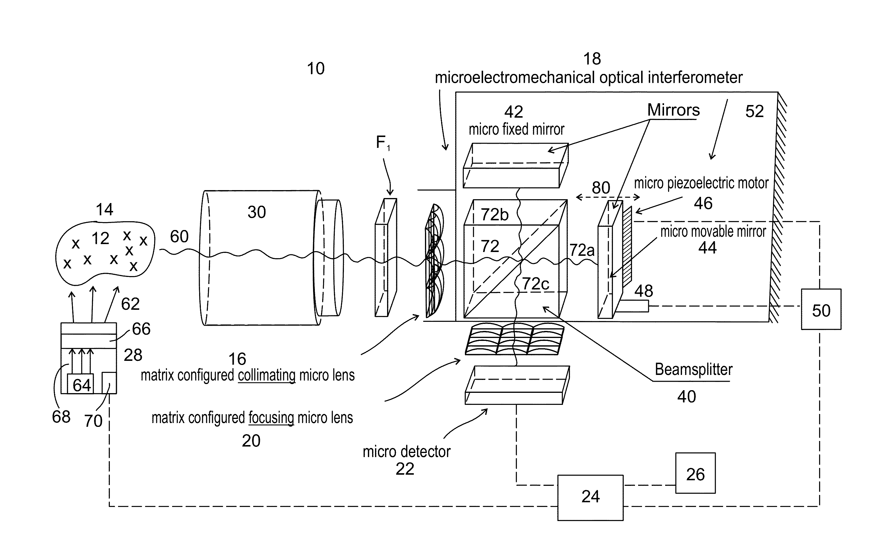
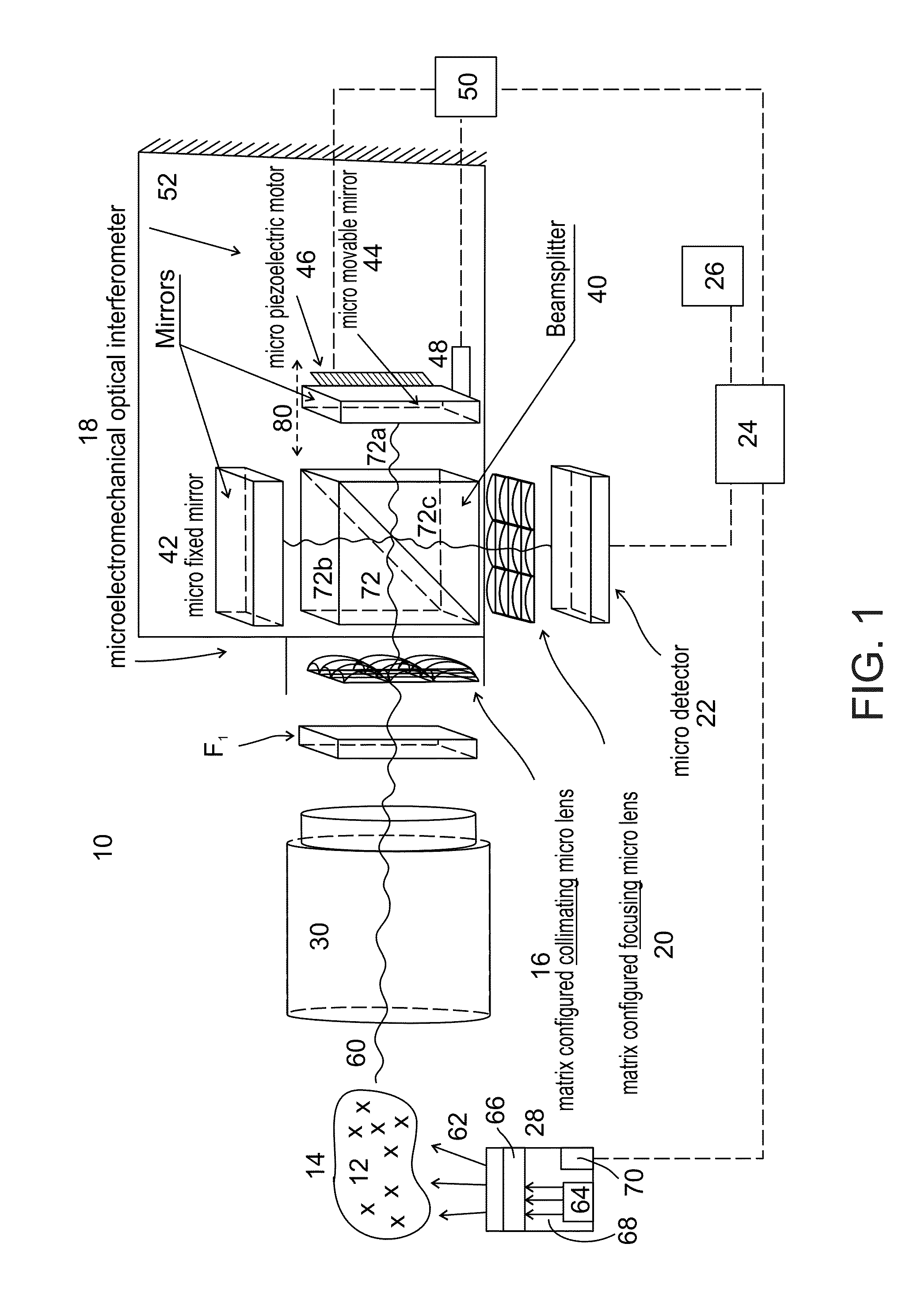
The present invention is about a microelectromechanical system for hyper-spectral imaging and analysis. It includes a matrix configured collimating micro lens, a microelectromechanical optical interferometer, a micro detector, and a micro central programming and control / data / information signal processing unit (micro-CPPU). The invention can be used on a miniaturized or micro (sub-centimeter) scale for analyzing objects in real-time or off-line. It can be used in various fields such as agricultural products, environmental matters, pharmaceutical products, and food products. The invention overcomes limitations of previous hyper-spectral imaging techniques and provides a more efficient and accurate way to analyze objects.

Problems solved by technology

However, such exemplary embodiments are limited in applications requiring or / and involving high speed high resolution hyper-spectral imaging and analyzing on a miniaturized or ‘micro’ (sub-centimeter [1 cm (10 mm) or less], or sub-millimeter) scale.
Main limitations relate to size and dimensional aspects of the various electromechanical or / and optical design, structural, and functional (operational), characteristics, properties, and features, of the optical interferometer as part of the overall hyper-spectral imaging and analysis system.

Method used


Image

  • Microelectromechanical system (MEMS) and (MEM) optical interferometer for hyper-spectral imaging and analysis
  • Microelectromechanical system (MEMS) and (MEM) optical interferometer for hyper-spectral imaging and analysis
  • Microelectromechanical system (MEMS) and (MEM) optical interferometer for hyper-spectral imaging and analysis

Examples


Embodiment Construction

[0039]The present invention, in some embodiments thereof, relates to the fields of hyper-spectral imaging and analysis, and microelectromechanical systems (MEMS) and microelectromechanical (MEM) components thereof, and more particularly, but not exclusively, to a microelectromechanical system (MEMS) for hyper-spectral imaging and analysis, and a microelectromechanical (MEM) optical interferometer for hyper-spectral imaging and analysis for hyper-spectral imaging and analysis.

[0040]Exemplary embodiments of the present invention are generally applicable for on-line (e.g., real time or near-real time) or off-line hyper-spectral imaging and analyzing, on a miniaturized or ‘micro’ (sub-centimeter [1 cm (10 mm) or less], or sub-millimeter) scale, essentially any type or kind of biological, physical, or / and chemical, (i.e., biophysicochemical) object (entity, material, substance, or structure), wherein the object is composed or made up of essentially any type, kind, and number of species o...


PUM


Abstract

A microelectromechanical system (MEMS) (10), and a microelectromechanical (MEM) optical interferometer (18), for hyper-spectral imaging and analysis. System (10) includes matrix configured collimating micro lens (16), for receiving and collimating electromagnetic radiation (60) emitted by objects (12) in a scene or sample (14); microelectromechanical optical interferometer (18), for forming divided collimated object emission beam (72) having an optical path difference, and for generating an interference image exiting optical interferometer (18); matrix configured focusing micro lens (20); micro detector (22), for detecting and recording generated interference images; and micro central programming and signal processing unit (24). Applicable for on-line (e.g., real time or near-real time) or off-line hyper-spectral imaging and analyzing, on a miniaturized or ‘micro’ (sub-centimeter [1 cm (10 mm) or less], or sub-millimeter) scale, essentially any types or kinds of biological, physical, or / and chemical, (i.e., biophysicochemical) objects.

Description

FIELD OF THE INVENTION[0001]The present invention, in some embodiments thereof, relates to the fields of hyper-spectral imaging and analysis, and microelectromechanical systems (MEMS) and microelectromechanical (MEM) components thereof, and more particularly, but not exclusively, to a microelectromechanical system (MEMS) for hyper-spectral imaging and analysis, and a microelectromechanical (MEM) optical interferometer for hyper-spectral imaging and analysis.[0002]Exemplary embodiments of the present invention are generally applicable for on-line (e.g., real time or near-real time) or off-line hyper-spectral imaging and analyzing, on a miniaturized or ‘micro’ (sub-centimeter [1 cm (10 mm) or less], or sub-millimeter) scale, essentially any type or kind of biological, physical, or / and chemical, (i.e., biophysicochemical) object (entity, material, substance, or structure), wherein the object is composed or made up of essentially any type, kind, and number of species or components, whic...

Claims


Application Information

Patent Timeline
IPC IPC(8): G01J3/45B81B7/02G01B9/02
CPCG01J3/0208G01J3/0256G01J3/4535G02B7/182G02B26/06B81B7/02G01B9/02049G01J3/45G02B3/0056G01J3/06G01J2003/064G01J3/0202G01B9/02
Inventor MOSHE, DANNY S.
Owner GREENVISION SYST
Learn More