Marine environment antifouling system and methods

a marine environment and antifouling technology, applied in the field of antifouling systems, can solve the problems of increasing the chance of failure, affecting the measurement accuracy of instruments, and the coating will not work, so as to reduce the surface fouling, improve the efficiency, and prolong the life

Active Publication Date: 2014-03-20
WOODS HOLE OCEANOGRAPHIC INSTITUTION
View PDF2 Cites 17 Cited by
  • Summary
  • Abstract
  • Description
  • Claims
  • Application Information

AI Technical Summary

Benefits of technology

[0007]The present invention relates to systems and methods for reducing fouling of a surface of an optically transparent element with a light source. By using LEDs, such a system may be more efficient, have a longer lifetime, and be more compact than traditional systems. The systems and methods may be further augmented by varying wavelengths and duty cycle.
[0010]In another aspect, the invention relates to a method for reducing fouling of a surface of an optically transparent element subjected to a marine environment. The method includes providing an LED source for emitting UV-C radiation, driving the LED source to emit UV-C radiation, and directing emitted UV-C radiation toward the optically transparent element.

Problems solved by technology

However, in many circumstances a coating will not work.
For example, windows of a submerged precision optical instrument cannot be coated due to concerns with obstructing the clarity of the windows, thereby affecting the instrument's measurements.
Another approach is to remove the organisms manually, e.g., by scrubbing wiping akin to a windshield wiper, but the use of mechanical components can increase the opportunities for failure and introduce additional complexity and cost into the system.
While certain types of UUVs are tethered by cable to the seafloor observatories, the tethered UUVs have a short range of motion and are limited by the length of the tether.
Acoustic communication systems, however, tend to be limited by low bandwidth and high latency, and do not permit video or other high-rate data transfers.

Method used


Image

  • Marine environment antifouling system and methods
  • Marine environment antifouling system and methods
  • Marine environment antifouling system and methods

Examples


Embodiment Construction

[0019]The invention may be better understood by reference to the following detailed description, taken in conjunction with the figures. Various embodiments of the invention relate to a system for eliminating biofilm on a surface. Other configurations and variants will be apparent to those skilled in the art from the teachings herein.

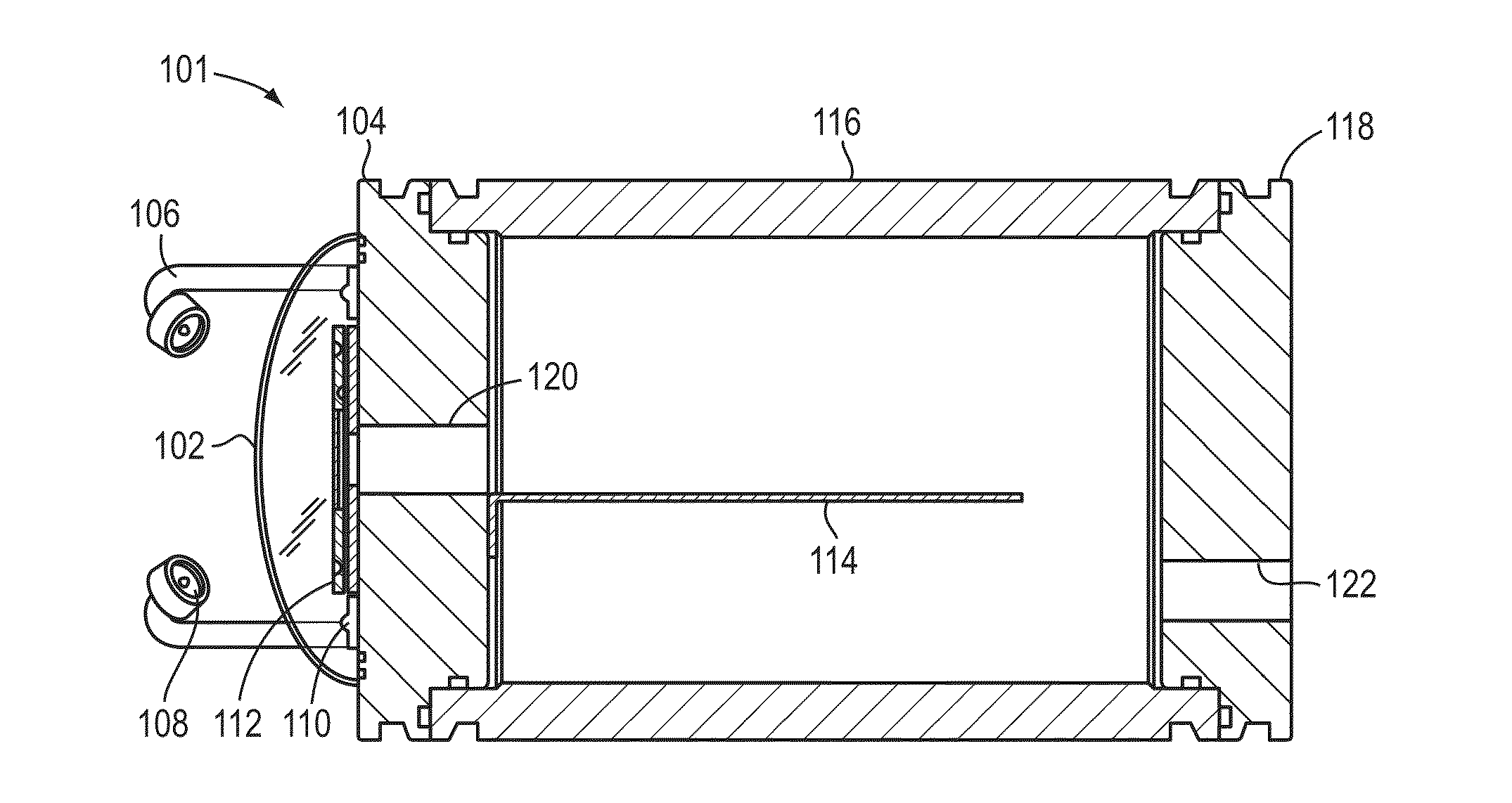
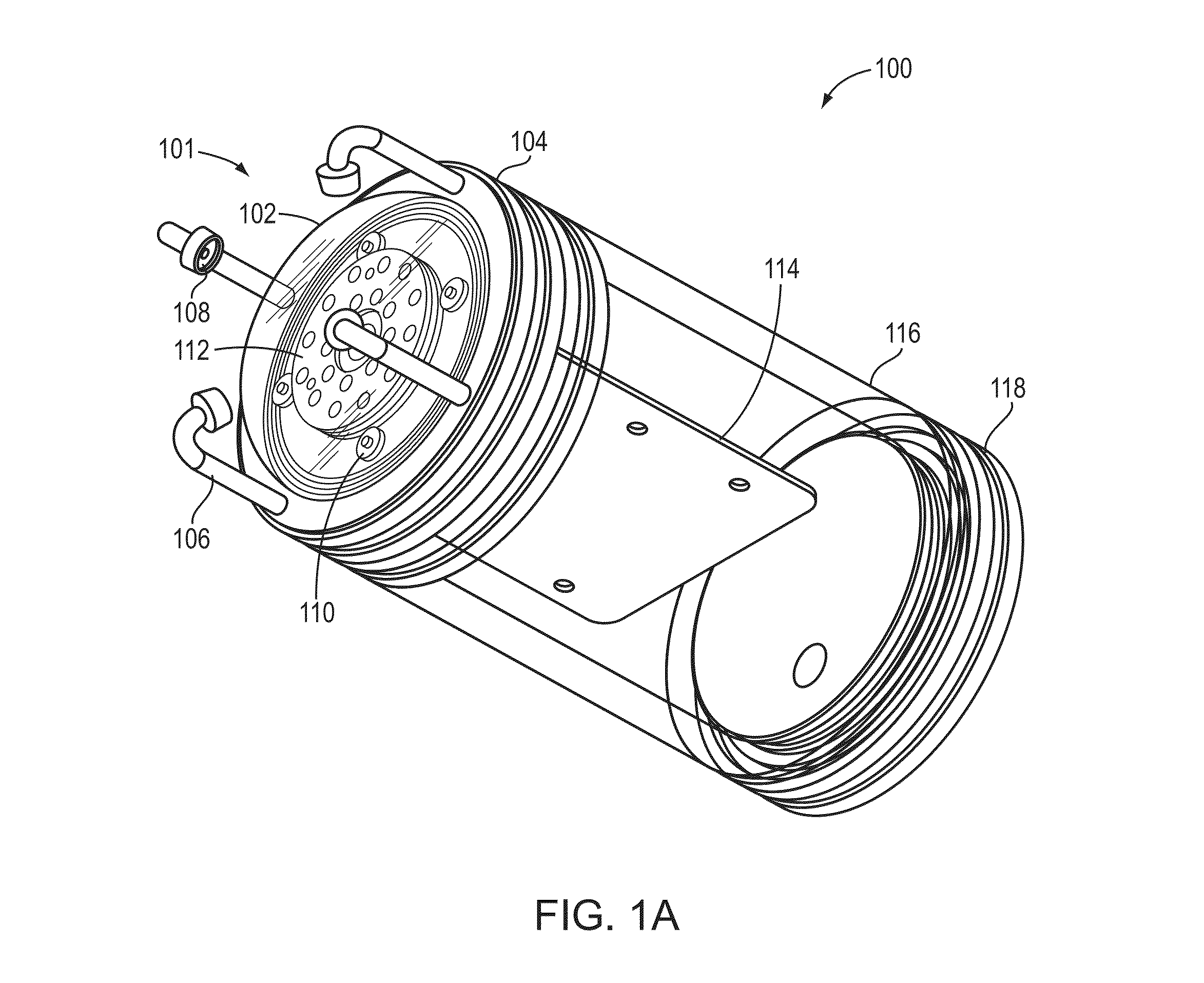
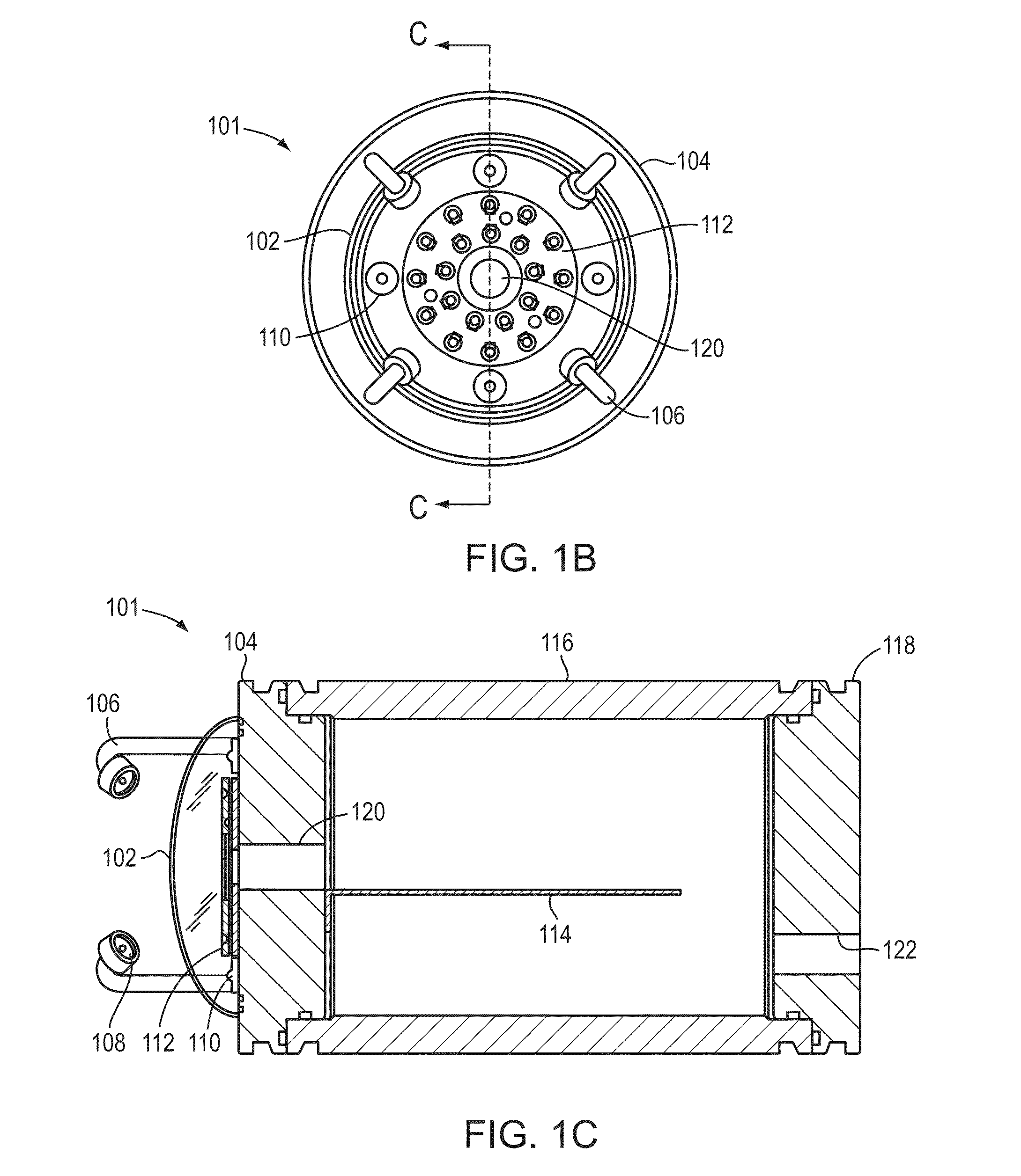
[0020]FIG. 1A depicts an optical modem (or transmitter assembly) 100 with a system 101 for reducing fouling of a surface of an optically transparent element 102 in a marine environment. The outer surface of the optically transparent element may be in contact with marine fluid, making this surface particularly vulnerable to developing biofilm that supports larger organism bio-fouling. The system 101 may be configured to remove / prevent the formation of biofilm. The optically transparent element 102 allows for the transmission of light therethrough, enabling communications and sensors reliant on optics to operate within the interior of the optical modem 100...


PUM


Abstract

The present invention relates to systems and methods for reducing fouling of a surface of an optically transparent element with a light source. According to one aspect, the invention is a system including an LED for emitting UV-C radiation, a mount for directing emitted UV-C radiation toward the optically transparent element, and control circuitry for driving the LED. The system may be used to remove a desired amount of biofilm.

Description

RELATED APPLICATIONS[0001]This application claims priority to and the benefit of U.S. Provisional Patent Application Ser. No. 61 / 671,426 filed on Jul. 13, 2012, the disclosure of which is hereby incorporated herein by reference in its entirety.STATEMENT REGARDING FEDERALLY SPONSORED RESEARCH OR DEVELOPMENT[0002]Federal funds awarded by the National Science Foundation under Grant Nos. OCE-0942835 and OCE-0737958 contributed to making this invention. The U.S. Government has certain rights herein.FIELD OF THE INVENTION[0003]The present invention relates generally to antifouling systems and, more specifically, to antifouling systems operating in situ with an LED light source.BACKGROUND OF THE INVENTION[0004]The growth and feeding of biofouling organisms (e.g., forming a hard substrate community) inhibits the operational characteristics of industrial objects, such as lenses. Several approaches are used to address this problem, including using coatings. However, in many circumstances a co...

Claims


Application Information

Patent Timeline
Patent Type & Authority Applications(United States)
IPC IPC(8): G02B27/00B08B7/00
CPCB08B7/0057G02B27/0006B63B59/04B63B59/08G02B23/22
Inventor FARR, NORMAN ERWINPONTBRIAND, CLIFFORD THOMASPETERS, TIMOTHY GOODWIN
Owner WOODS HOLE OCEANOGRAPHIC INSTITUTION
Why Eureka
Try Eureka