Power Supply Circuit
- Summary
- Abstract
- Description
- Claims
- Application Information
AI Technical Summary
Benefits of technology
Problems solved by technology
Method used
Image


Examples
first embodiment
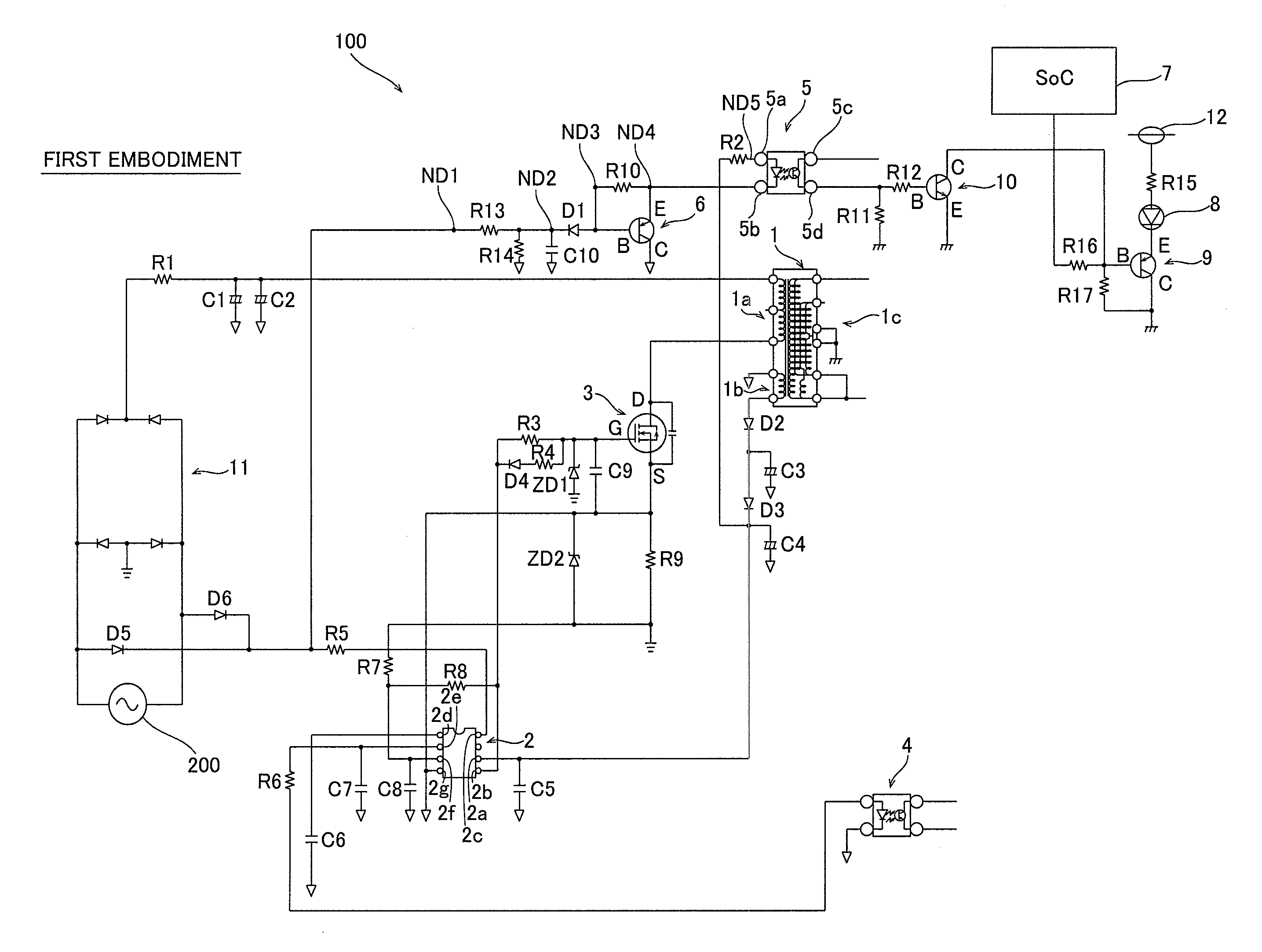
[0041]The schematic circuit structure of a power supply circuit 100 according to a first embodiment is now described with reference to FIG. 1.
[0042]The power supply circuit 100 includes a transformer 1 to which the voltage of an alternating current source 200 is input, comparison means 110 for comparing a voltage value based on the voltage input to the transformer 1 with a voltage value based on the full-wave rectified voltage of the alternating current source 200, a load circuit 130 to which power output from the secondary side of the transformer 1 is supplied, and stop means 120 for stopping power supply to the load circuit 130 on the basis of the comparison result of the comparison means 110.
[0043]The detailed structure of the power supply circuit 100 according to the first embodiment of the present invention is now described with reference to FIG. 2.
[0044]The power supply circuit 100 according to the first embodiment includes the transformer 1 including a primary winding 1a, an ...
second embodiment
[0072]A power supply circuit 101 according to a second embodiment is now described with reference to FIG. 6. This power supply circuit 101 according to the second embodiment has a diode D1 whose anode side is connected to an auxiliary winding 1b, unlike the power supply circuit 100 according to the aforementioned first embodiment having the diode D1 whose anode side is connected to the photocoupler 5.
[0073]As shown in FIG. 6, in the power supply circuit 101, the auxiliary winding 1b is connected to the anode side of the diode D1 through resistors R18 and R10. The power supply circuit 101 is so configured that the full-wave rectified voltage of an alternating current source 200 is input to the cathode side of the diode D1 through diodes D5 and D6 and a resistor R13.
[0074]The anode side of an LED 8 is connected to a power supply 12 through a resistor R15. The cathode side of the LED 8 is connected to the emitter E of a transistor 9 including a bipolar transistor. The base B of the tra...
third embodiment
[0080]A power supply circuit 102 according to a third embodiment is now described with reference to FIG. 8. This power supply circuit 102 according to the third embodiment is a self-excited power supply circuit, unlike the power supply circuits 100 and 101 that are the separately-excited power supply circuits according to the aforementioned first and second embodiments.
[0081]As shown in FIG. 8, in the power supply circuit 102, a transformer 21 includes a primary winding 21a, an auxiliary winding 21b, and a secondary winding 21c. A first end of the auxiliary winding 21b is connected to a capacitor C11 and is grounded. According to the third embodiment, the power supply circuit 102 is the self-excited power supply circuit so configured that a voltage based on the voltage of the auxiliary winding 21b is input to the gate G of a transistor 22 configured to adjust the amount of current flowing to the primary winding 21a of the transformer 21 in order to perform on-off control of the tran...
PUM
 Abstract
Description
Claims
Application Information