Fuel cell system and method of controlling the fuel cell system

a fuel cell and system technology, applied in the direction of fuel cell control, fuel cells, electrical equipment, etc., can solve the problems of lowering the performance of discharging water, large quantity of stagnant water cannot be discharged, and high probability of large quantity of stagnant water present, so as to maintain the desired power generation performance and discharge simple and reliably

Active Publication Date: 2014-03-20
HONDA MOTOR CO LTD
View PDF4 Cites 16 Cited by
  • Summary
  • Abstract
  • Description
  • Claims
  • Application Information

AI Technical Summary

Benefits of technology

[0018]In the present invention, in the case where the water content in the fuel cell is excessive, a long drive cycle for injecting the fuel gas to the fuel cell is set, and a large quantity of fuel gas is set for

Problems solved by technology

However, after high load operation continued for a certain period of time, in the case where operation switched to low load operation, it is highly probable that a large quantity of stagnant water is present.
Therefore, in the small flow rate injector, since the quantity of injected

Method used


Image

  • Fuel cell system and method of controlling the fuel cell system
  • Fuel cell system and method of controlling the fuel cell system
  • Fuel cell system and method of controlling the fuel cell system

Examples


first embodiment

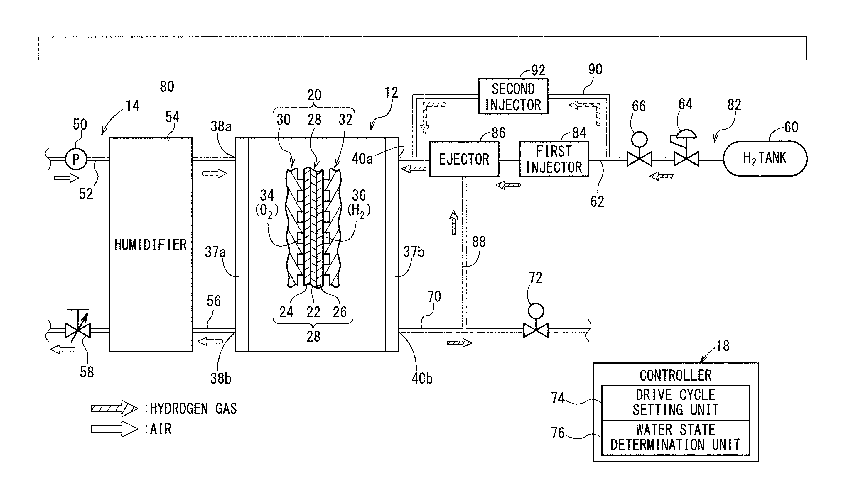
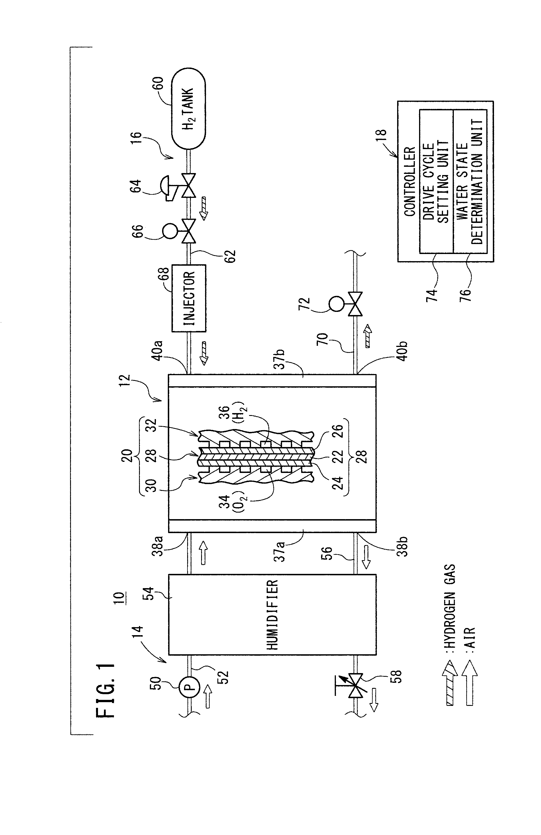
[0032]As shown in FIG. 1, a fuel cell system 10 according to the present invention includes a fuel cell stack 12, an oxygen-containing gas supply apparatus 14 for supplying an oxygen-containing gas to the fuel cell stack 12, a fuel gas supply apparatus 16 for supplying a fuel gas to the fuel cell stack 12, and a controller (control device) 18 for controlling the entire fuel cell system 10. For example, the fuel cell system 10 is mounted in a fuel cell vehicle (not shown) such as a fuel cell electric automobile.

[0033]The fuel cell stack 12 is formed by stacking a plurality of fuel cells 20 together. Each of the fuel cells 20 includes a membrane electrode assembly (MEA) 28. The membrane electrode assembly 28 includes a cathode 24, an anode 26, and a solid polymer electrolyte membrane 22 interposed between the cathode 24 and the anode 26. For example, the solid polymer electrolyte membrane 22 is a fluorine based electrolyte membrane or a hydrocarbon based electrolyte membrane.

[0034]Eac...

second embodiment

[0043]A pressure reducing value 64, an interruption valve 66, and an electronically controlled injector (fuel gas supply unit) 68 are provided in the hydrogen supply channel 62. The injector 68 injects the hydrogen gas supplied from the hydrogen tank 60 cyclically, for supplying the hydrogen gas to the fuel cell stack 12 through the hydrogen supply channel 62. The fuel gas supply unit is not limited to the injector 68, and various devices can be used. This is also the case with a second embodiment described later.

[0044]An off gas channel (fuel gas discharge pipe) 70 is connected to the fuel gas outlet manifold 40b, and a purge valve 72 is connected to a certain position in the off gas channel 70.

[0045]The controller 18 has a drive cycle setting unit 74 for setting the drive cycle of the injector 68 based on the load of the fuel cell stack 12, and a water state determination unit 76 for determining whether or not the quantity of water content in the fuel cell stack 12 is a predetermi...


PUM


Abstract

A fuel gas supply apparatus of a fuel cell system includes a pressure reducing valve, an interruption valve, and an injector in a hydrogen supply channel. A controller of the fuel cell system includes a drive cycle setting unit for setting the drive cycle of the injector based on a load of the fuel cell stack, and a water state determination unit for determining whether or not quantity of water content in the fuel cell is excessive by determining whether or not the quantity of water content is a predetermined quantity or more.

Description

CROSS-REFERENCE TO RELATED APPLICATION[0001]This application is based upon and claims the benefit of priority from Japanese Patent Application No. 2012-202917 filed on Sep. 14, 2012, the contents of which are incorporated herein by reference.BACKGROUND OF THE INVENTION[0002]1. Field of the Invention[0003]The present invention relates to a fuel cell system including a fuel cell for generating electrical energy by electrochemical reactions of an oxygen-containing gas and a fuel gas, an oxygen-containing gas supply apparatus for supplying the oxygen-containing gas, a fuel gas supply apparatus for supplying the fuel gas, and a control device. Further, the present invention relates to a method of controlling the fuel cell system.[0004]2. Description of the Related Art[0005]In general, a fuel cell is a system for obtaining direct current electrical energy by electrical chemical reactions of a fuel gas (gas chiefly containing hydrogen such as a hydrogen gas) supplied to an anode of the fue...

Claims


Application Information

Patent Timeline
IPC IPC(8): H01M8/04
CPCH01M8/04604H01M8/04753H01M8/04097H01M8/045H01M8/04619H01M2008/1095Y02E60/50
Inventor OHGAMI, OSAMUUEDA, KENICHIROMIYATA, KOICHIROOGAWA, JUMPEIYAMAMOTO, TAKASHI
Owner HONDA MOTOR CO LTD
Why Eureka
Try Eureka