Separator for fuel cell, fuel cell, and manufacturing method of separator

Active Publication Date: 2016-05-19
TOYOTA JIDOSHA KK +1
View PDF2 Cites 1 Cited by
  • Summary
  • Abstract
  • Description
  • Claims
  • Application Information

AI Technical Summary

Benefits of technology

The patent describes a new design for a separator used in fuel cells. The design includes an adhesive layer that is formed prior to the rubber molded body, which prevents burrs from forming during the manufacturing process. This adhesive layer is formed over an area that includes the outer edge of the separator central area, which is the area where the rubber molded body is die-casted. By using this design, the burrs formed during the manufacturing process are reduced, and the adhesive layer helps to prevent the burrs from causing damage to the rubber molded body. This results in a more durable and reliable fuel cell.

Problems solved by technology

Although the approach described above can reduce the formation of burrs at parts other than the air vent portion, the cutting of the burrs at the air vent portion may cause damages to the gasket.
Therefore, a burr cutting mechanism with a higher positioning precision is required, and a careful burr cutting work is necessary, resulting in a complicated process as a whole.
Since the rubber molded body is formed by die-casting the die-casting rubber material using the die, burrs may be formed during the die-casting in a membrane shape connected with the rubber molded body due to leaked die-casting rubber material when the die-casting rubber material leaks from between the die and the adhesive layer.
However, if the burr is released from the rubber molded body, it may cause adverse effects to the functions of the rubber molded body.
Therefore, the leaked die-casting rubber material becomes difficult to move toward the separator central area portion side, compared with a formed part of the central area portion side rubber molded body.
Other than described above, since the burr which connects the central area portion side rubber molded body with the rubber molded body is adhered to the outer edge portion by the adhesive layer, it becomes difficult to cause the release and exfoliation of the burr.

Method used


Image

  • Separator for fuel cell, fuel cell, and manufacturing method of separator
  • Separator for fuel cell, fuel cell, and manufacturing method of separator
  • Separator for fuel cell, fuel cell, and manufacturing method of separator

Examples


Embodiment Construction

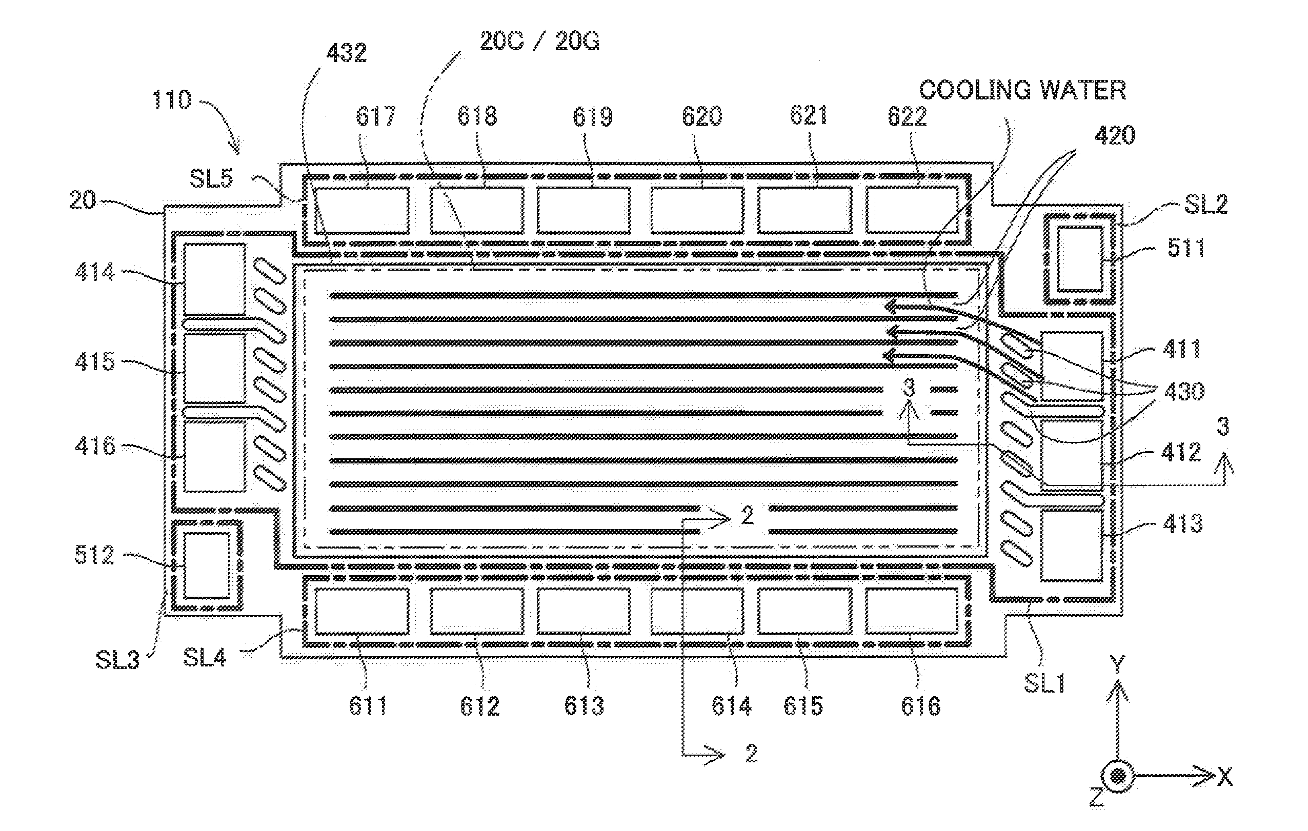
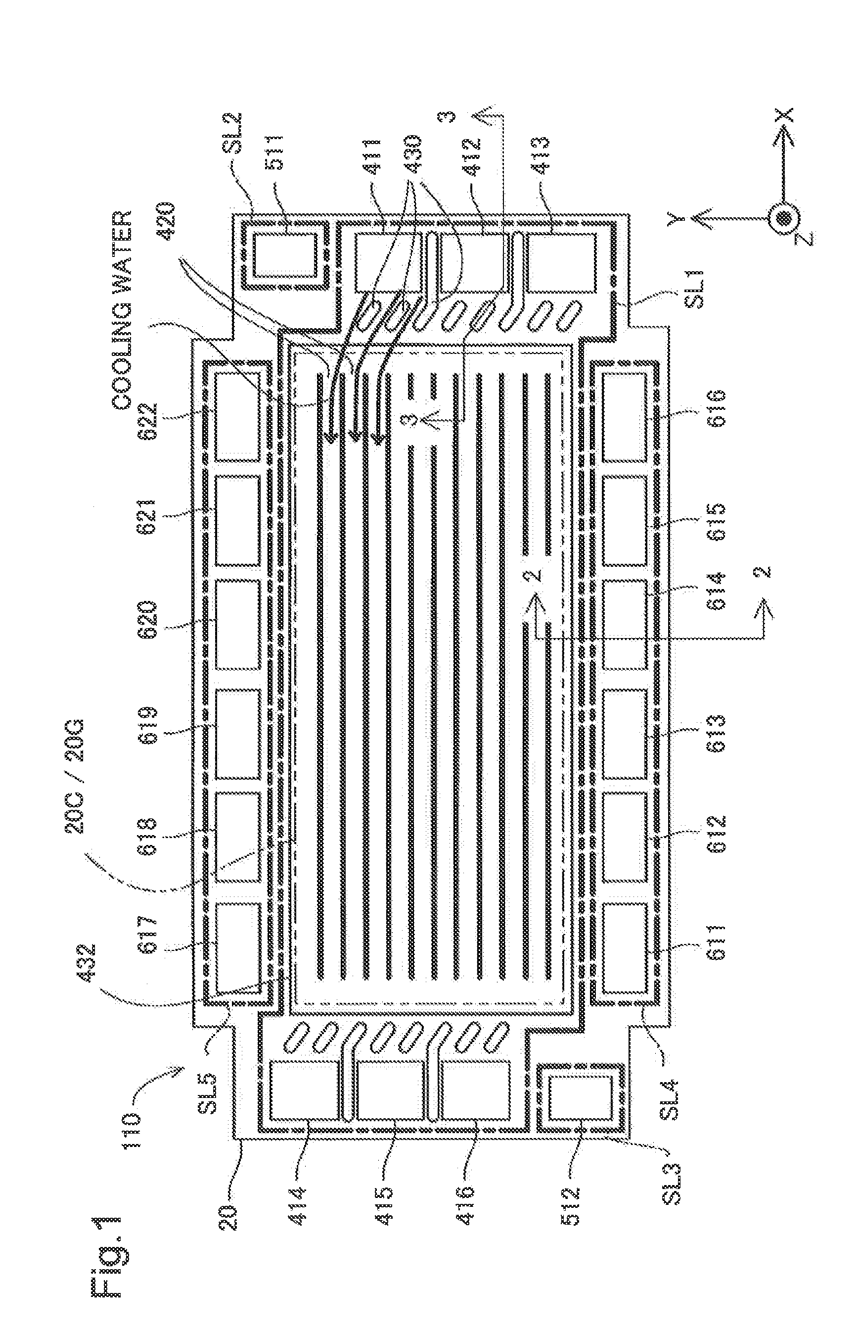
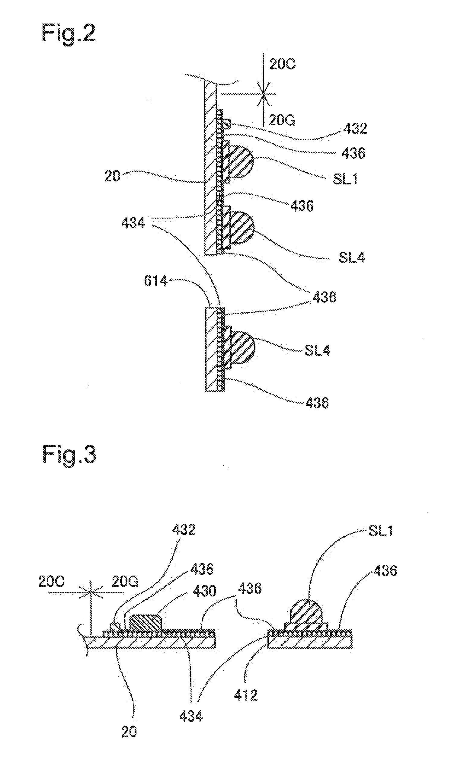
[0022]Hereinafter, one embodiment of the present invention is described with reference to the accompanying drawings. FIG. 1 is a plan view illustrating a unit cell 110 as one embodiment of the invention, FIG. 2 is a cross-sectional view illustrating a first separator 20 taken along a line 2-2 in FIG. 1, and FIG. 3 is a cross-sectional view illustrating the first separator 20 taken along a line 3-3 in FIG. 1. A fuel cell has a stacked structure in which a plurality of unit cells 110 are stacked in Z-directions illustrated in FIG. 1. FIG. 1 illustrates the first separator 20, and each unit cell 110 is fabricated by stacking a membrane electrode assembly and a second separator onto the first separator 20 in a deeper direction of the drawing. The membrane electrode assembly is fabricated by joining catalyst electrode layers to both sides of an electrolyte membrane, and a central portion thereof serves as a power generating area.

[0023]Each unit cell 110 is provided with cooling water man...


PUM

PropertyMeasurementUnit
Areaaaaaaaaaaa
Heightaaaaaaaaaa

Abstract

A separator for a fuel cell, to be disposed opposing to a membrane electrode assembly, is provided. The separator includes a separator central area portion opposing to a center area of the membrane electrode assembly that concerns generating power, an outer edge portion located in an outer edge of the separator central area portion, a rubber molded body made of rubber, the rubber molded body being formed in the outer edge portion by die-casting a die-casting rubber material using die, and an adhesive layer formed in the outer edge portion, for adhering the rubber molded body to the outer edge portion. The adhesive layer is formed over an adhesive layer area that includes and is larger than an area where the rubber molded body is die-casted in the outer edge portion. Thus, a disadvantage due to burrs which are generated when die-casting the rubber molded body can be reduced.

Description

CROSS-REFERENCE TO RELATED APPLICATION[0001]The present application claims priority from Japanese application P2014-230339 filed on Nov. 13, 2014, the content of which is hereby incorporated by reference into this application.BACKGROUND[0002]1. Field[0003]The present invention relates to a separator for a fuel cell, the fuel cell, and a method of manufacturing the separator.[0004]2. Related Art[0005]A fuel cell has a stacked structure in which a plurality of unit cells, each of which serves as a power generator, are stacked. Each unit cell includes separators, and the separators divide the unit cell from other adjacent cells. Each separator involves in supply and discharge of fuel gas, oxygen containing gas, and cooling water to / from the unit cell, and is provided with a gasket for sealing passages of the gas and cooling water. The gasket is formed by die-casting rubberlike elastic material. Since the die-casting often involves leaks of the die-casting rubber material from cavities ...

Claims


Application Information

Patent Timeline
IPC IPC(8): H01M8/02
CPCH01M8/0247H01M8/0297H01M8/0258H01M8/0202H01M8/0228H01M8/0273H01M8/0276H01M2008/1095Y02P70/50Y02E60/50
Inventor KADONO, HIDEYASATO, KENJIKURIHARA, TAKUYASHIZUKU, FUMISHIGEITAKURA, HIROKIAOKI, TAKAHIRO
Owner TOYOTA JIDOSHA KK
Why Eureka
Try Eureka