Trailer access point pairing

a technology of access points and trailers, applied in the field of electronic braking systems of trailers, can solve the problems of large depots, prone to human error, and high degree of manual input, and achieve the effect of reducing the number of vehicles in the depository

Active Publication Date: 2014-03-20
KNORR BREMSE SYST FOR COMML VEHICLES
View PDF9 Cites 72 Cited by
  • Summary
  • Abstract
  • Description
  • Claims
  • Application Information

AI Technical Summary

Benefits of technology

[0014]The system of the present invention advantageously avoids the undesired pairing of tractors and trailers, which might otherwise occur in trailer depots and similar locations. In this exemplary embodiment, the inventio

Problems solved by technology

However, depots have become larger with many having dozens or even hundreds of trailers on site and allocated a job at any one time.
In particular for larger companies, it has become difficult to track the trailer use in the depot due to the sheer number of trailers and due to the use of standardized trail

Method used


Image

  • Trailer access point pairing
  • Trailer access point pairing
  • Trailer access point pairing

Examples


Embodiment Construction

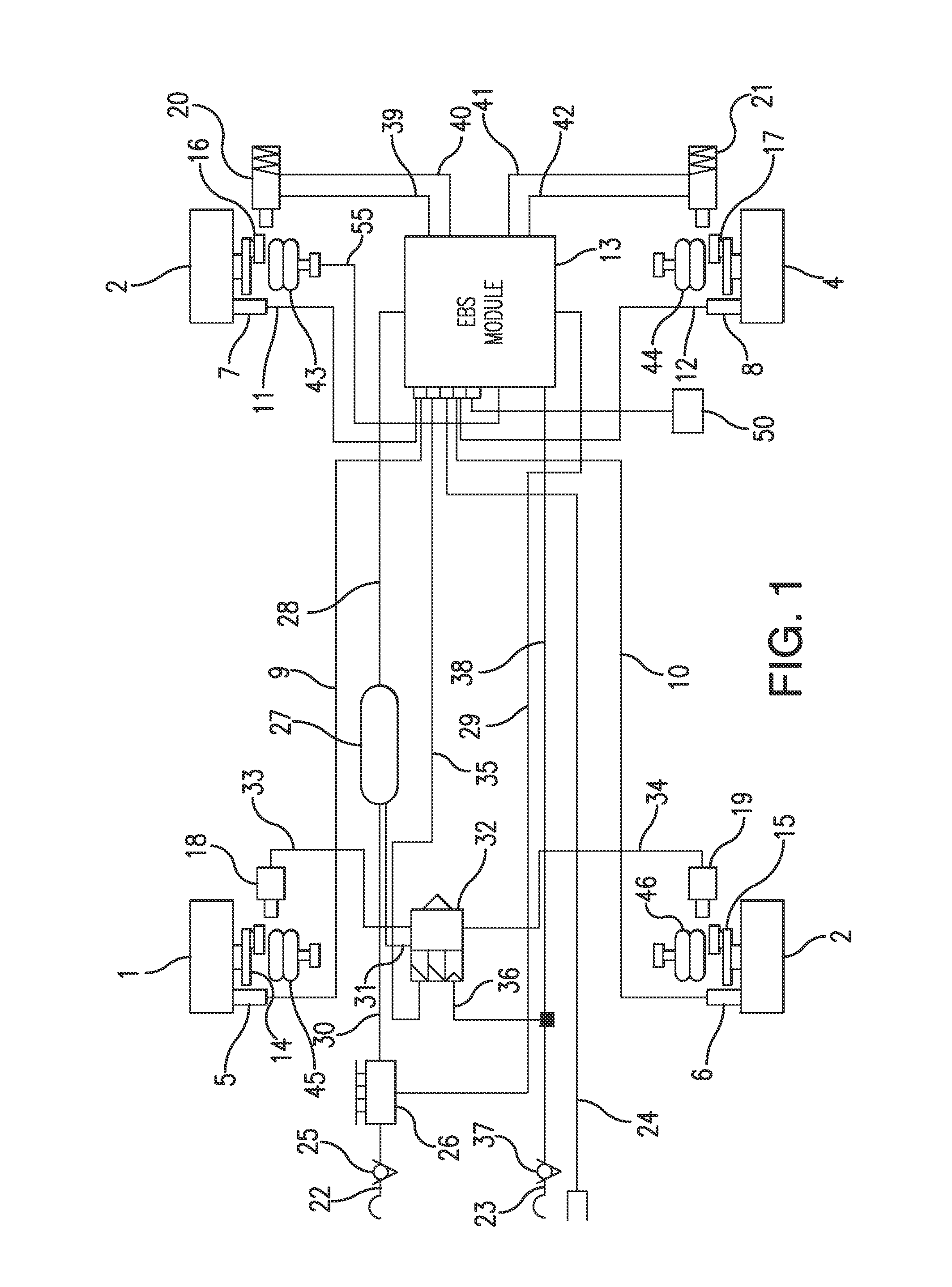
[0018]The utility vehicle trailer has a steerable front axle with front wheels 1, 2 and a rear axle with rear wheels 3, 4. Rotational wheel speed sensors 5-8 are in each case assigned to the front wheels 1, 2 and the rear wheels 3, 4, and are connected by way of electric lines 9-12 with an electropneumatic brake pressure control module 13 (EBS module) which is primarily assigned to the rear axle brakes. One brake 14-17 is in each case assigned to the front wheels 1, 2 and the rear wheels 3, 4, which brake 14-17 can be applied by brake cylinders 18, 19 of the front axle or spring-loaded brake cylinders 20, 21 of the rear axle.

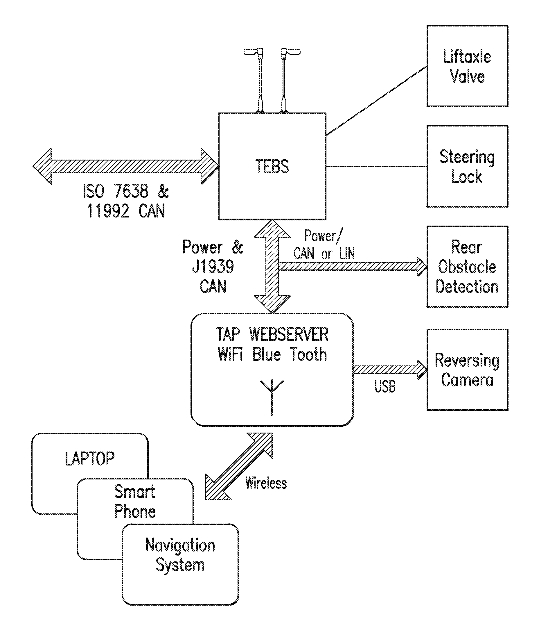
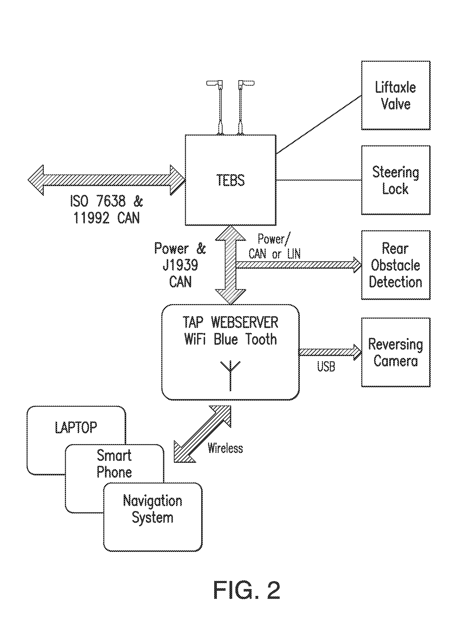
[0019]The braking system of the trailer vehicle can be connected by way of three connections, specifically a pneumatic supply line connection 22, a pneumatic control line connection 23 and an electric control connection 24, with the braking system of a. tractor or a further trailer. The electric control line 24 provides the ISO 11992 CAN data connection.

[0020]Th...


PUM


Abstract

A trailer electronic braking system comprising a braking device capable of generating a braking force on a wheel on the trailer. The braking force is applied to the brake cylinders and is controllable by a braking ECU, which braking ECU is connected to a standards compliant communication bus on the trailer. The ECU is adapted to receive data inputs from sensors on the trailer. The system further includes an arrangement to interface to trailer electronics and a communications interface. In use, the arrangement transmits a request to the device for a driver to apply a predetermined condition to the trailer to enable control functions to be actuated from a remote device.

Description

RELATED APPLICATION INFORMATION[0001]The present application claims priority to and the benefit of United Kingdom Patent Application No. 1216571.8, filed on Sep. 17, 2012, the disclosure of which is incorporated herein by reference.FIELD OF THE INVENTION[0002]The present invention relates to a trailer electronic braking system.BACKGROUND INFORMATION[0003]The trend in modern distribution systems is towards having large distribution depots located on the outskirts of towns and cities near main trunk roads. These large distribution depots have a number of significant logistical advantages for the operators in terms of stock control and speed and ease of distribution of goods. However, depots have become larger with many having dozens or even hundreds of trailers on site and allocated a job at any one time. In particular for larger companies, it has become difficult to track the trailer use in the depot due to the sheer number of trailers and due to the use of standardized trailers havi...

Claims


Application Information

Patent Timeline
IPC IPC(8): B60T7/00
CPCB60T7/00B60T7/16B60T7/18B60T7/20B60T7/22B60T8/323B60T8/1708B60T8/1887B62D53/00B60G2300/04B60G2600/202
Inventor FRY, MATTHEW
Owner KNORR BREMSE SYST FOR COMML VEHICLES
Why Eureka
Try Eureka