Waterproof wire connectors

a technology of wire connectors and wire connectors, which is applied in the direction of dustproof/splashproof/drip-proof/waterproof/flameproof connection, connection end caps, etc., can solve the problems of limited clamping force of push-in wire connectors, lack of inherent aggressiveness of clamping forces generated by push-in wire connectors, and inability to increase the for

Inactive Publication Date: 2014-03-27
KING JR HERBERT +2
View PDF6 Cites 7 Cited by
  • Summary
  • Abstract
  • Description
  • Claims
  • Application Information

AI Technical Summary

Benefits of technology

[0010]A waterproof wire connector comprising a push in wire connector having a wire chamber therein for receiving and forming electrical engagement with an electrical wire axially inserted therein with the wire connector having a wire port with a self healing member extending across the entry to the wire port to prevent moisture from entering the wire connector whereby pushing the wire into the wire connector forces the end of an electrical wire to pierce the self healing member. One continues to push on the electrical wire until the end of the electrical wire is in electrical engagement with an electrical conductor in the wire connector. The coaction between the self healing member extending across the entry to wire port and the wire covering extending thereto has been found that through use of self healing material one can form and maintain an annular seal which is sufficiently waterproof to prevent moisture from coming into contact with the wire connection in the push-in wire connector. Consequently, using a layer of self healing material one can form a waterproof push-in wire connector without the need for a sealant in the wire connector and without losing the benefit of the one step method of forming an electrical connection through one continuous motion of inserting a wire into the push-in wire connector.

Problems solved by technology

The clamping force holding the wire in electrical contact with bus strip and the electrical conductor of the push-in wire connector are determined by the resilient force of the electrical conductor and can not be increased by more aggressive action such as in twist-on wire connectors since the axial force applied to flex the resilient conductor in a push-in wire connector is limited by the stiffness of the wire.
The wire clamping force in the push-in wire connector is limited because the axial resistance of the resilient conductor must not be so large so as to bend the electrical wire during the insertion process.
Consequently, clamping forces generated by push-in wire connectors lack the inherent aggressive nature of other connectors that can force sealant away from contact areas between conductors in order to form a low resistance electrical contact.
However, the lack of an ability to increase the force on the contact regions between the edge, the bus strip and the wire limit the ability to enhance the electrical connection in a push-in wire through use of additional force.

Method used


Image

  • Waterproof wire connectors
  • Waterproof wire connectors
  • Waterproof wire connectors

Examples


Embodiment Construction

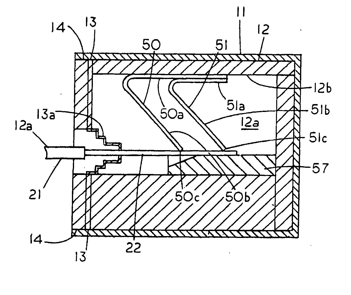
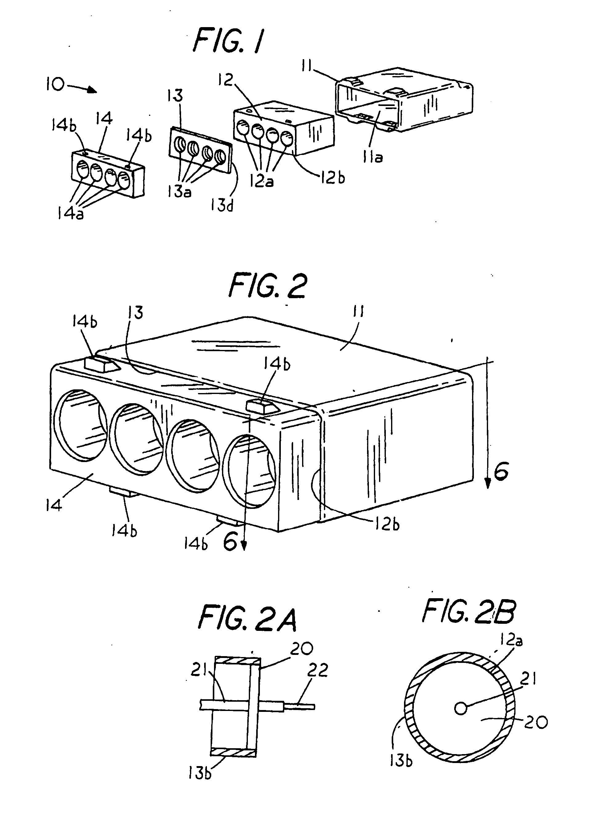
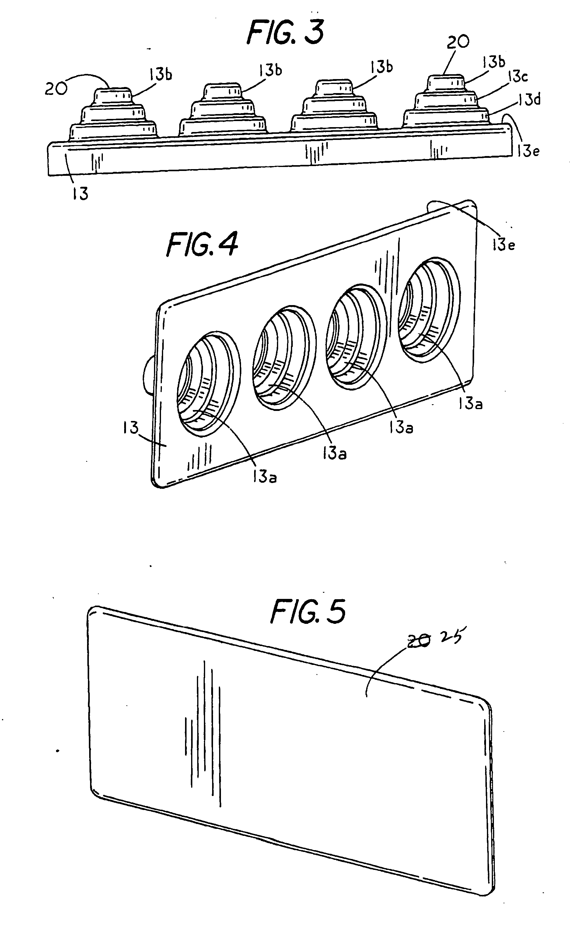
[0024]FIG. 1 shows an exploded view of a self healing push-in waterproof wire connector 10 comprising a rectangular shaped electrically insulated housing 11 having a pocket 11a for receiving a push-in wire connector 12. Push-in wire connector 12 includes an end face 12b having a set of four cylindrical wire ports 12a that provides access passages to internal wire engaging members located within the interior of wire connector 12. A feature of the push-in wire connectors is that in one motion a wire can be electrically connected to an electrical connector or bus strip merely by axially inserting a wire into a wire port until the wire engages a resilient member located within the wire connector.

[0025]In order to avoid water corrosion of the electrical connection within a wire connector it is important that the interior of the wire connector be kept free from moisture. One of the ways of protecting an electrical connection from moisture is shown in U.S. Pat. No. 7,972,166, which contain...


PUM

PropertyMeasurementUnit
thicknessaaaaaaaaaa
self healingaaaaaaaaaa
waterproofingaaaaaaaaaa

Abstract

A waterproof wire connector comprising a push in wire connector having a wire chamber therein for receiving and forming electrical engagement with an electrical wire axially inserted therein with the wire connector having a wire port with a self healing member extending across the entry to the wire port to prevent moisture from entering the wire connector whereby pushing the wire into the wire connector forces the end of an electrical wire to pierce the self healing member.

Description

CROSS REFERENCE TO RELATED APPLICATIONS[0001]This application claims priority from provisional application Ser. No. 61 / 628,205 filed Oct. 26, 2011.STATEMENT REGARDING FEDERALLY SPONSORED RESEARCH OR DEVELOPMENT[0002]NoneREFERENCE TO A MICROFICHE APPENDIX[0003]NoneBACKGROUND OF THE INVENTION[0004]Numerous types of electrical wire connectors for forming bared ends of electrical wires into a waterproof electrical connection are known in the art. One type of electrical connector relies on inserting the wires into a sealant located between a terminal block and a terminal screw and then squeezing the bared ends of the wire by rotating the terminal screw. The more the terminal screw is tightening the greater the squeezing and hence the better the electrical connection between the bared wire end and the terminal screw.[0005]Another type of electrical wire connector is a twist-on wire connector that can be used to form a waterproof electrical connection through rotation of the electrical wir...

Claims


Application Information

Patent Timeline
Patent Type & Authority Applications(United States)
IPC IPC(8): H01R13/52H01R43/00
CPCH01R43/005H01R13/52H01R4/22H01R13/5208Y10T29/49185H01R4/48185
Inventor KING, JR., HERBERTHINER, WILLIAMKEEVEN, JAMES
Owner KING JR HERBERT
Why Eureka
Try Eureka