Process for liquefaction of natural gas

Inactive Publication Date: 2014-03-27
GASCONSULT
View PDF8 Cites 28 Cited by
  • Summary
  • Abstract
  • Description
  • Claims
  • Application Information

AI Technical Summary

Benefits of technology

[0017]Relative to the two above-mentioned patents, an inventive step in the present application consists of identifying operating conditions for the two expanders (the precooling expander and the liquefying

Problems solved by technology

However expander processes have certain drawbacks:until recently, limited capacity and experience with

Method used


Image

  • Process for liquefaction of natural gas
  • Process for liquefaction of natural gas
  • Process for liquefaction of natural gas

Examples


Example

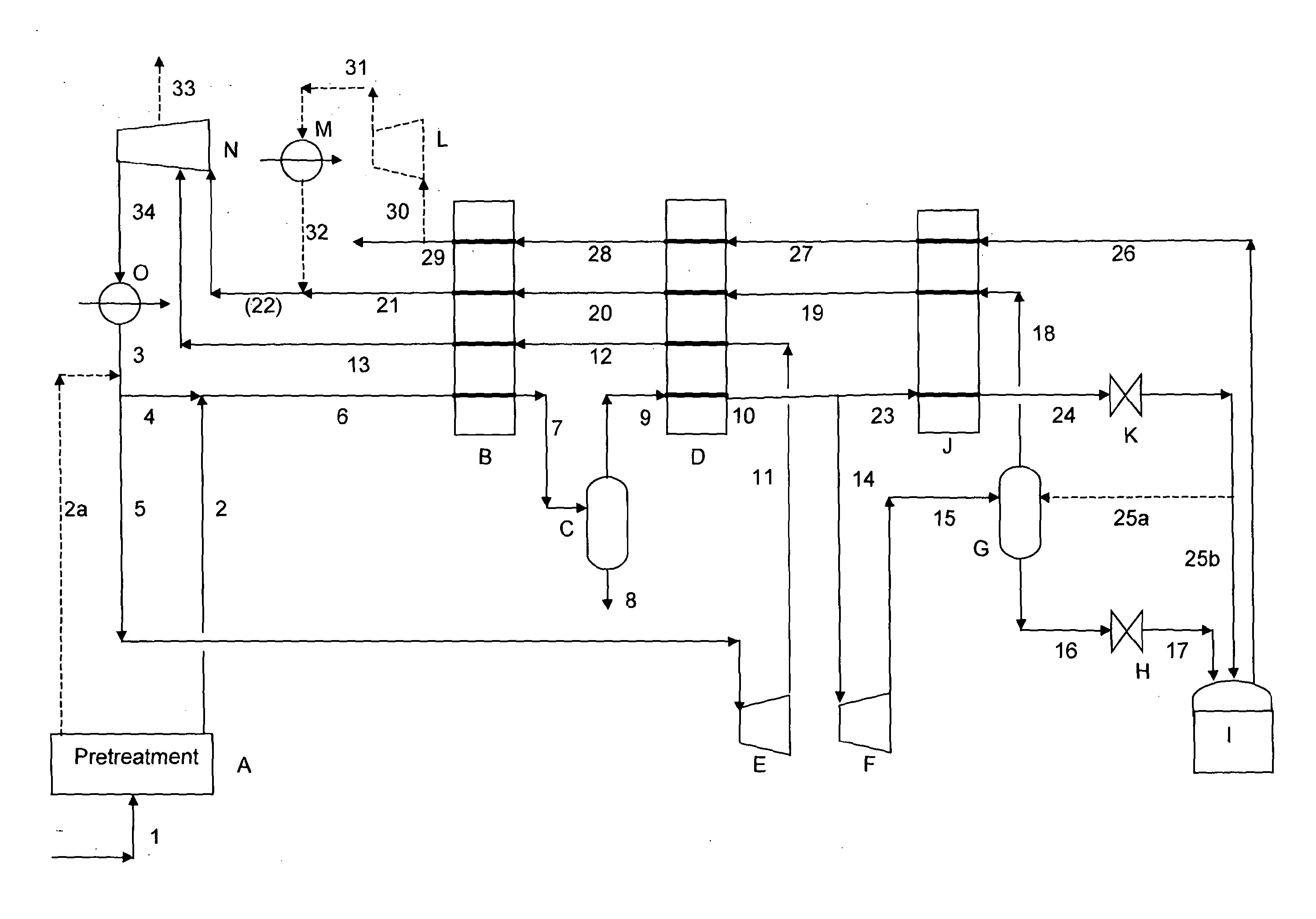
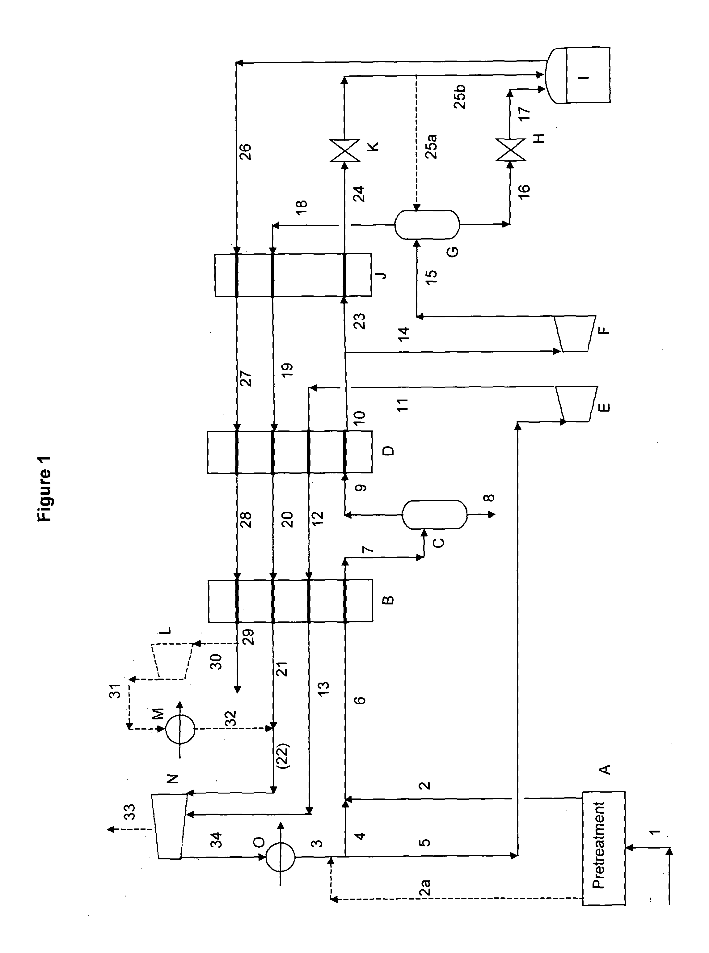
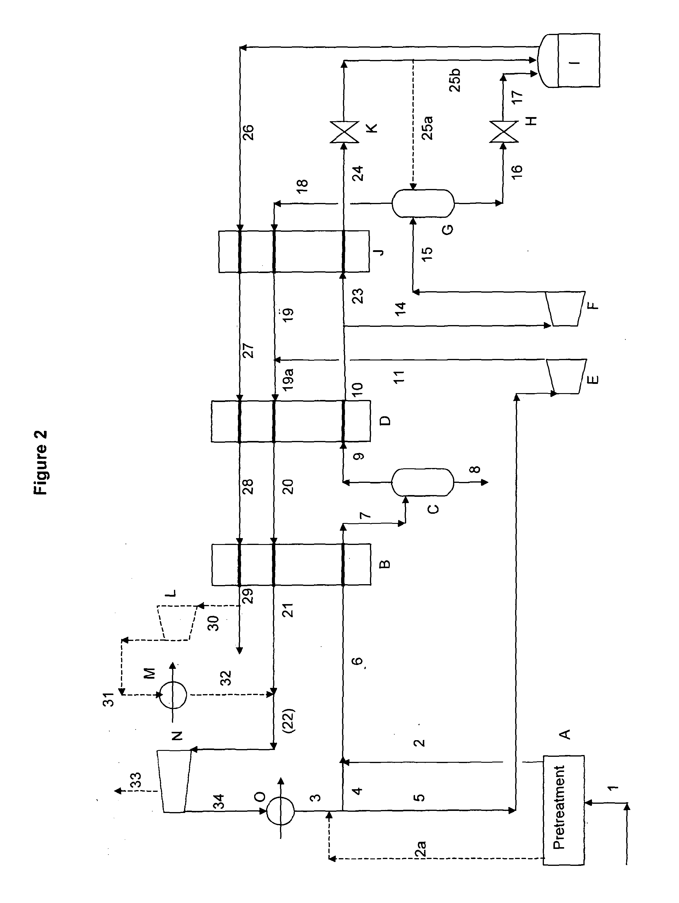
[0020]According to the invention, there is provided a process for liquefying natural gas or other methane-rich gases. The feed gas, generally at a pressure of from 40 (4 MPa) to 100 bar (10 MPa), is liquefied to give LNG product at approx 1 bar (0.1 MPa) / −161° C. by the expander-based plant configuration described above Sand comprising:[0021]cooling feed gas and recycle gas (mentioned below) in a first step by means of a first heat exchanger and in a first work expander; the heat exchanger having an outlet temperature in the range of −50° to −80° C., preferably −60° to −70° C.; the expander having a lower outlet temperature than that of the heat exchanger; the expander having its outlet stream reheated in a cold passage of the said heat exchanger and then recompressed to form part of the above mentioned recycle gas.[0022]passing the cooled outlet stream from the said first heat exchanger partly into a hot passage in a second heat exchanger, wherein it is essentially condensed, and p...


PUM


Abstract

A process comprising: cooling natural gas with a heat exchanger and a first expander. The heat exchanger cools the feed natural gas to temperature higher than the outlet temperature of the expander, reheating the expander outlet stream in a first cold passage of the heat exchanger to slightly below the temperature of the feed natural gas to the heat exchanger, passing the cold outlet stream from the heat exchanger into a second expander wherein it is partly liquefied, separating the outlet stream of second expander into liquid and vapour fractions, collecting the liquid fraction for use as LNG product, reheating the vapour fraction in a second cold side passage of the heat exchanger to substantially the same temperature as the temperature of the feed natural gas to the heat exchanger, recycling the reheated vapour fraction partly as feed to the first expander and partly as feed to the heat exchanger.

Description

FIELD OF THE INVENTION[0001]The present invention relates to a method for liquefying methane-rich gas and, more particularly but not exclusively, relates to a method for producing liquefied natural gas (LNG).BACKGROUND TO THE INVENTION[0002]Liquefaction of natural gas can practically be achieved by:[0003]evaporation of liquid refrigerants[0004]work expansion of gases in expansion machines (expanders).[0005]Evaporation of liquid refrigerants gives the lowest power requirement and is the basis of the widely used Cascade and Mixed Refrigerant LNG processes.[0006]Expander-based LNG installations are simple, compact, low in weight and can avoid the importation / preparation / storage of liquid refrigerants. These characteristics are attractive for smaller scale applications, particularly offshore, where low hydrocarbon inventory is desirable from safety considerations. However expander processes have certain drawbacks:[0007]until recently, limited capacity and experience with expanders[0008]...

Claims


Application Information

Patent Timeline
IPC IPC(8): F25J1/00
CPCF25J1/0022F25J1/0035F25J1/0037F25J1/004F25J1/0202F25J1/023F25J1/0254F25J2220/62F25J2220/64F25J2270/06F25J1/0227F25J1/0242F25J1/0281F25J1/0283F25J2240/82F25J2270/906F25J1/0211F25J5/00F25J1/00
Inventor MAUNDER, ANTHONY DWIGHTSKINNER, GEOFFREY FREDERICK
Owner GASCONSULT
Why Eureka
Try Eureka