Wireless power transmission apparatus and direct drive type system including the apparatus

a technology of power transmission apparatus and direct drive, which is applied in the direction of transformer/inductance details, transformer/inductance circuit, inductance, etc., can solve the problems of affecting the quality of products, noise of peripheral members, dust generation by abrasion, etc., and achieves the effect of reducing the resonance q value and being easy to adjus

Active Publication Date: 2014-03-27
DENSO WAVE INC +1
View PDF4 Cites 17 Cited by
  • Summary
  • Abstract
  • Description
  • Claims
  • Application Information

AI Technical Summary

Benefits of technology

[0113]In the present embodiment, the plate-like electrode member 143 is provided on a rear surface side which is an opposite side of the coil member 142, with the interposition of the substrate 141. Thus, with the substrate 141 being sandwiched between the coil member 142 and the electrode member 143, the capacitors 162, 163, 165 and 166 are formed. Further, the coil member 142 provided to the substrate 141 forms a reactance. Formation of these capacitors 162, 163, 165 and 166 and the reactance induces resonance. Thus, the resonance frequency is adjusted by changing the overlap conditions, such as the size, shape and arrangement of the electrode member 143, the thickness of the substrate 141, and the like, between the electrode member 143 and the coil member 142. Accordingly, the resonance frequency can be easily adjusted without causing increase in the size of parts, complication of processing steps and reduction in the Q value of resonance.
[0114]FIGS. 19 and 20 each show an electrode member of a field magnetic resonance coil member according to other embodiments.
[0115]As shown in these figures, in the coil assembly 140, the shape of the electrode member 143 can be changed. The electrode member 143 of the coil assembly 140 can be changed not only in its shape but also in the number of the electrode plates if only the number is two or more. Thus, change in the shape of the electrode member 143 of the coil assembly 140 leads to the change in the capacity of the capacitors formed between the electrode member 143 and the coil member 142, with the interposition of the substrate 141. In this way, the range of adjusting resonance frequency is expanded.
[0116]The present invention described so far is not limited to the embodiments described above but may be applied to various embodiments within a scope not departing from the spirit of the invention. For example, the shape and the number of turns of the coil member 142 may be optionally change.
[0117]Referring to FIGS. 21 to 28, hereinafter is described a third embodiment of a wireless power transmission apparatus and a direct drive type system including the apparatus.
[0118]As shown in FIGS. 21 to 23, a direct drive type robot 10B (hereinafter also just referred to as “robot 108”) includes a power transmission coil unit 211 (functioning as a rail member) and a power reception coil unit 212. The power transmission coil unit 211 and the power reception coil unit 212 configure the wireless power transmission apparatus. The robot 108 is set up in a production facility, a distribution facility and the like. The power transmission coil unit 211 includes a rail 213 in which a rack, not shown, is formed. The rail 213 is provided along the longitudinal direction of the power transmission coil unit 211. In the embodiment shown in FIGS. 21 to 23, the rail 213 has an upper end which is provided with a rack 214 functioning as a holding member.

Problems solved by technology

However, in a direct drive type robot including such a cable carrier, inevitably, the movable member moves being accompanied by the cable carrier.
The contact between the cable carrier and the peripheral members causes noises.
Further, the abrasion generates dust.
In particular, in manufacturing facilities for precision equipment, such as electronic equipment and semiconductors, dust may cause quality loss of the products.

Method used


Image

  • Wireless power transmission apparatus and direct drive type system including the apparatus
  • Wireless power transmission apparatus and direct drive type system including the apparatus
  • Wireless power transmission apparatus and direct drive type system including the apparatus

Examples


first embodiment

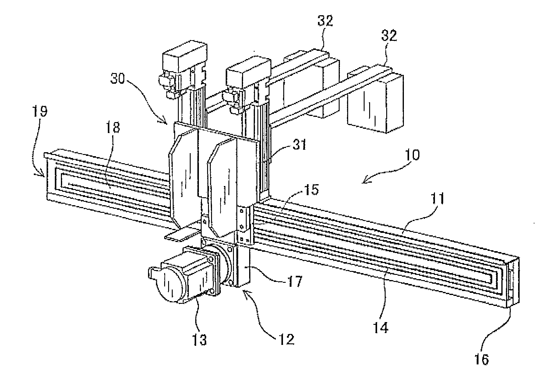
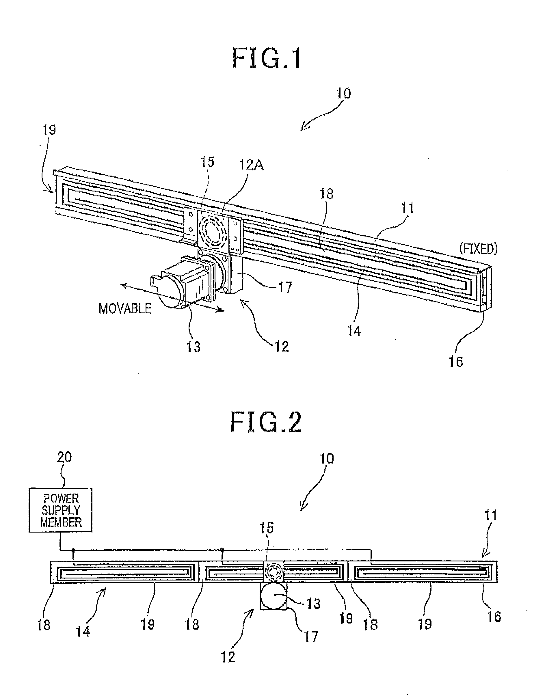
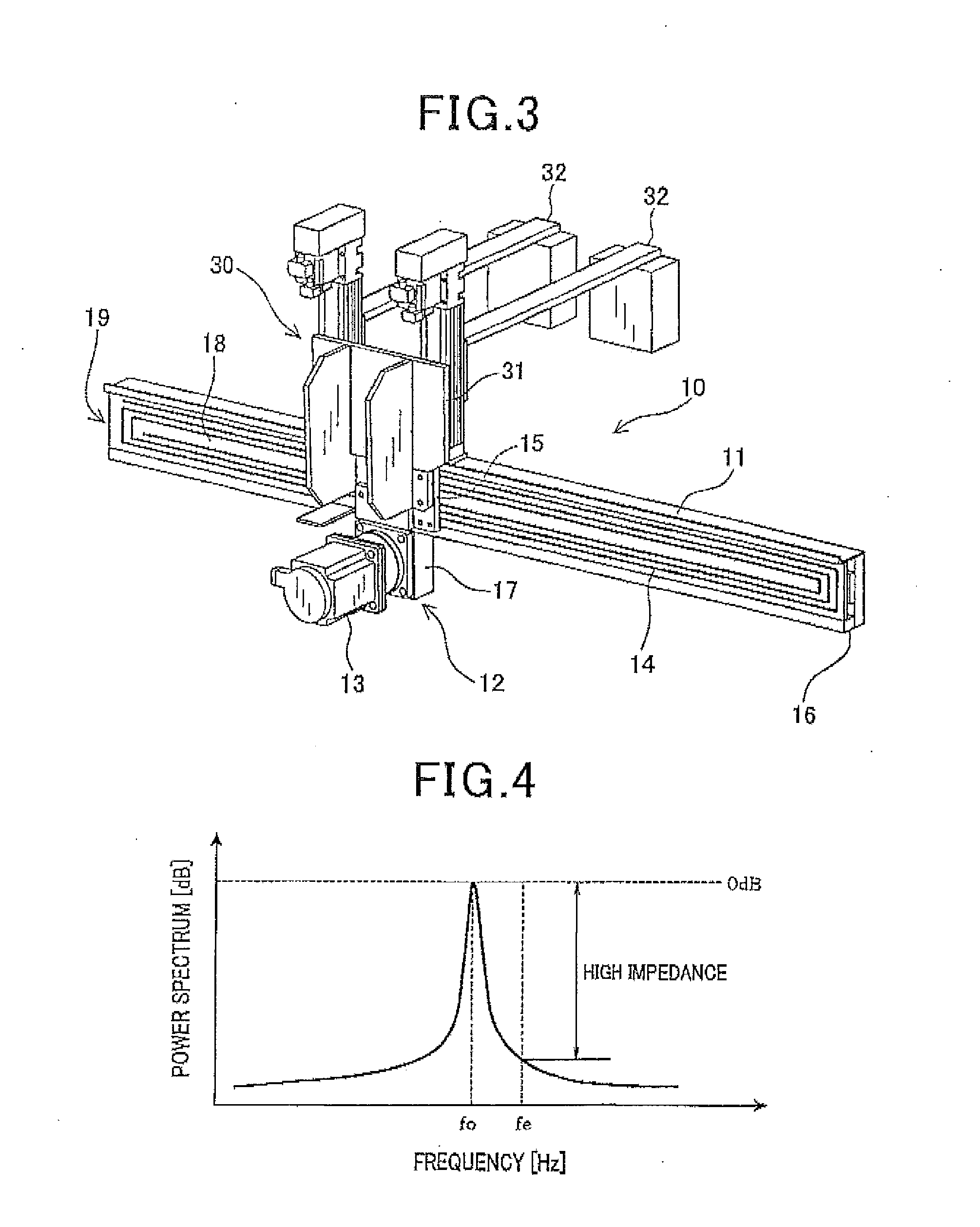
[0070]Referring to FIGS. 1 to 5, hereinafter is described a wireless power transmission apparatus and a direct drive type system including the apparatus, according to the first embodiment.

[0071]In the first and the subsequent embodiments as well as their modifications, the direct drive type system is described as a direct drive type robot. However, the direct drive type system of the present embodiment is riot necessarily limited to the system or machine called direct drive type robot. In other words, if only the system or machine includes a fixed rail member, a movable member that is movable along the rail member, being supported and guided by a guide, such as a linear guide, and a wireless power transmission means based on a magnetic resonant method for transmitting electric power from the rail member to the movable member, the naming “direct driven” and “robot” are not necessarily insisted on. Further, the system or machine does not necessarily have to be an industrial system. Fo...

second embodiment

[0095]Referring to FIGS. 8 to 18, hereinafter is described a second embodiment of a wireless power transmission apparatus and a direct drive type system including the apparatus.

[0096]The second and the subsequent embodiments as well as their modifications include description partially overlapped with the description of the configuration and effects of the first embodiment. However, taking account of the context and easiness of understanding of description, the partially overlapped description are permitted to remain without being removed. In addition, in the following descriptions, the power transmission and reception coils are also composed of planar coils, which are the same as those described in the first embodiment.

[0097]As shown in FIG. 8, similar to the configuration of the first embodiment, a direct drive type robot 10A (hereinafter also just referred to as “robot 10A”) that functions as a direct drive type system (direct drive type machine) includes a fixed unit 111 (functio...

third embodiment

[0117]Referring to FIGS. 21 to 28, hereinafter is described a third embodiment of a wireless power transmission apparatus and a direct drive type system including the apparatus.

[0118]As shown in FIGS. 21 to 23, a direct drive type robot 10B (hereinafter also just referred to as “robot 108”) includes a power transmission coil unit 211 (functioning as a rail member) and a power reception coil unit 212. The power transmission coil unit 211 and the power reception coil unit 212 configure the wireless power transmission apparatus. The robot 108 is set up in a production facility, a distribution facility and the like. The power transmission coil unit 211 includes a rail 213 in which a rack, not shown, is formed. The rail 213 is provided along the longitudinal direction of the power transmission coil unit 211. In the embodiment shown in FIGS. 21 to 23, the rail 213 has an upper end which is provided with a rack 214 functioning as a holding member.

[0119]The robot 10B includes a movable memb...


PUM

PropertyMeasurementUnit
diameteraaaaaaaaaa
diameteraaaaaaaaaa
thicknessaaaaaaaaaa

Abstract

A direct drive type system such as a direct drive type robot is provided. This system includes a rail member, a movable member guided by the rail member and movable along the rail member, and an electric motor to drive the movable member. The system includes a transmission coil and a reception coil. The transmission coil has plural transmission coil segments which are planar coils and arranged on and along the rail member. High-frequency power is supplied to the transmission coil from a power source. The reception coil is arranged on the movable member to be opposed to the transmission coil and configured to an area faced with each of the transmission coil segments, wherein the area is smaller than that of each transmission coil segment. The reception coil receives power from the transmission coil without contact by a magnetic resonance. The received power is supplied to the motor.

Description

CROSS-REFERENCE TO RELATED APPLICATION[0001]This application is based on and claims the benefit of priorities from earlier Japanese Patent Application Nos. 2012-212340, 2013-049060, 2013-050127 and 2013-049061 filed Sep. 26, 2012, Mar. 12, 2013, Mar. 22, 2013 and Mar. 12, 2013, the descriptions of which are incorporated herein by reference.BACKGROUND OF THE INVENTION[0002]1. Technical Filed[0003]The present invention relates to a wireless power transmission apparatus and a direct drive type system including the apparatus, and in particular to a wireless power transmission apparatus based on a magnetic resonant method and a direct drive type system including the apparatus.[0004]2. Related Art[0005]Direct drive type systems have been in heavy use such as in factories. Such a direct drive type system includes a movable member that can move along a fixed rail member. As an example of the direct drive type system, a direct drive type robot is well known as disclosed such as in JP-A-2009-...

Claims


Application Information

Patent Timeline
Patent Type & Authority Applications(United States)
IPC IPC(8): H01F38/14
CPCH01F38/14H01F27/2804
Inventor SUGINO, MASAYOSHIKONDOH, HIROSHITAKEDA, SHIGERUHASEO, YASUYUKIHAMASAKI, KEISUKE
Owner DENSO WAVE INC
Why Eureka
Try Eureka