Image projection and control apparatus and methods

a control apparatus and image technology, applied in the field of image and video projection systems, can solve problems such as the possibility of still being able to achieve geometrically unacceptable projections

Active Publication Date: 2014-03-27
VIDEA
View PDF4 Cites 13 Cited by
  • Summary
  • Abstract
  • Description
  • Claims
  • Application Information

AI Technical Summary

Benefits of technology

[0012]Further aspects of the invention enables the projected image to function as a “touch screen,” enabling a user to “select” points on the displayed image, enlarge and reduce dimensions, scroll, turn pages, and so forth. This feedback feature can be used to “stretch” the corners of the image (much like the “rubber-band” feature in graphic and drawing software enables the manipulation of the shape of an object), thereby enabling the user to “click-and-drag” the corners of the projected image to manually correct for keystone effects, or to assist in the auto-correction process for geometric correction. These embodiments include gesture recognition apparatus operative to recognize a gesture made by a finger, hand or other body part overlying the projected image in the view of the sensor, and control the device or projected image in response to the recognized gesture.
[0013]Assuming the projected image has x and y coordinates associated therewith, the gesture recognition apparatus is operative to determine the coordinates of a finger, hand or other body part overlying the projected image in the view of the sensor. The system is then operative to compare the position or movement thereof a finger, hand or other body part overlying the projected image to corresponding coordinates associated with the projected image to control the device or the projected image. The sensor may include an infrared imaging capability to assist in detecting a finger, hand or other body part overlying the projected image.

Problems solved by technology

Although there are many proposed solutions, including patents which are directed to keystone correction, they all make assumptions about the relationship between the projector and the projected image; if these assumptions are incorrect, a geometrically unacceptable projection may still result.

Method used


Image

  • Image projection and control apparatus and methods
  • Image projection and control apparatus and methods
  • Image projection and control apparatus and methods

Examples


Embodiment Construction

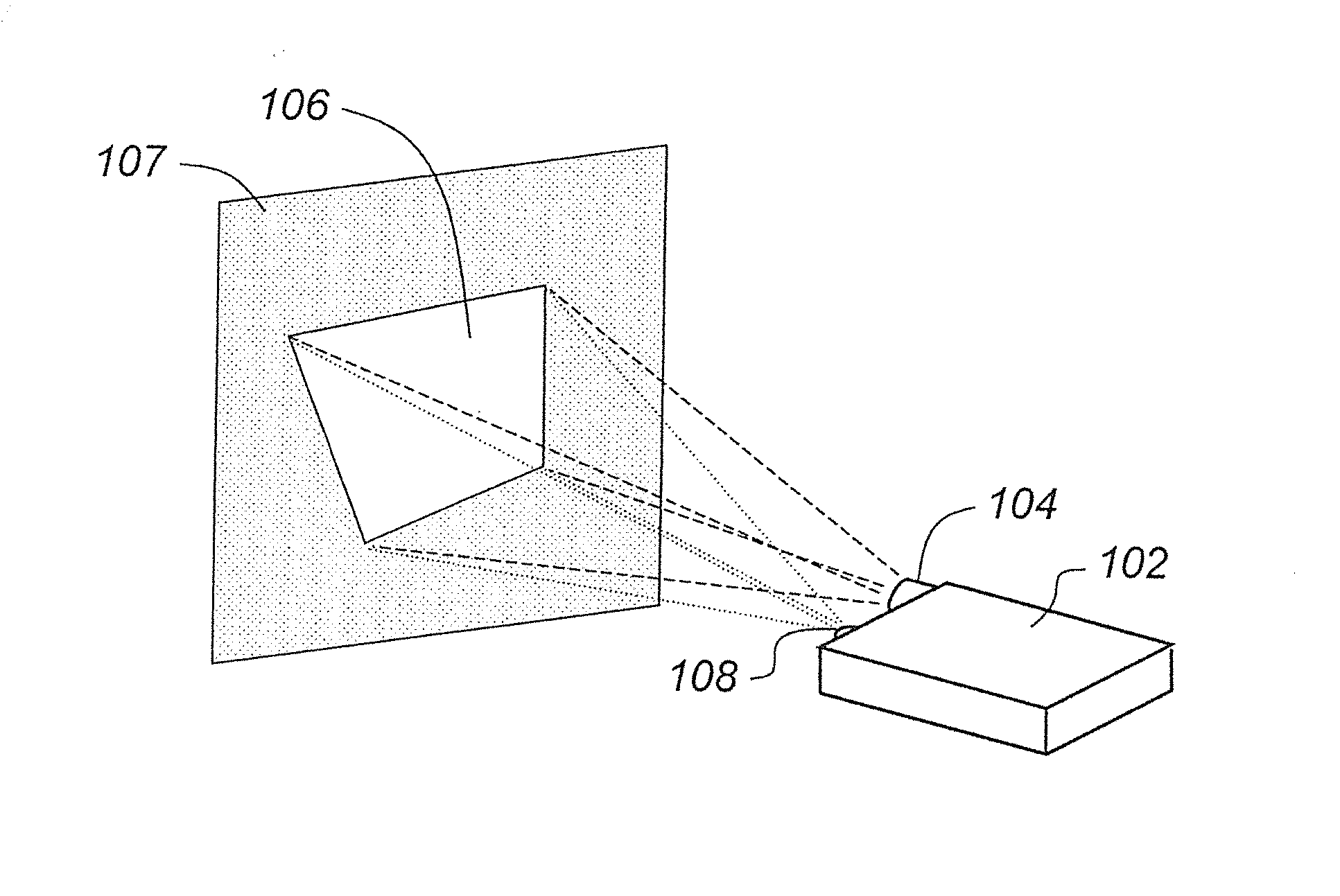
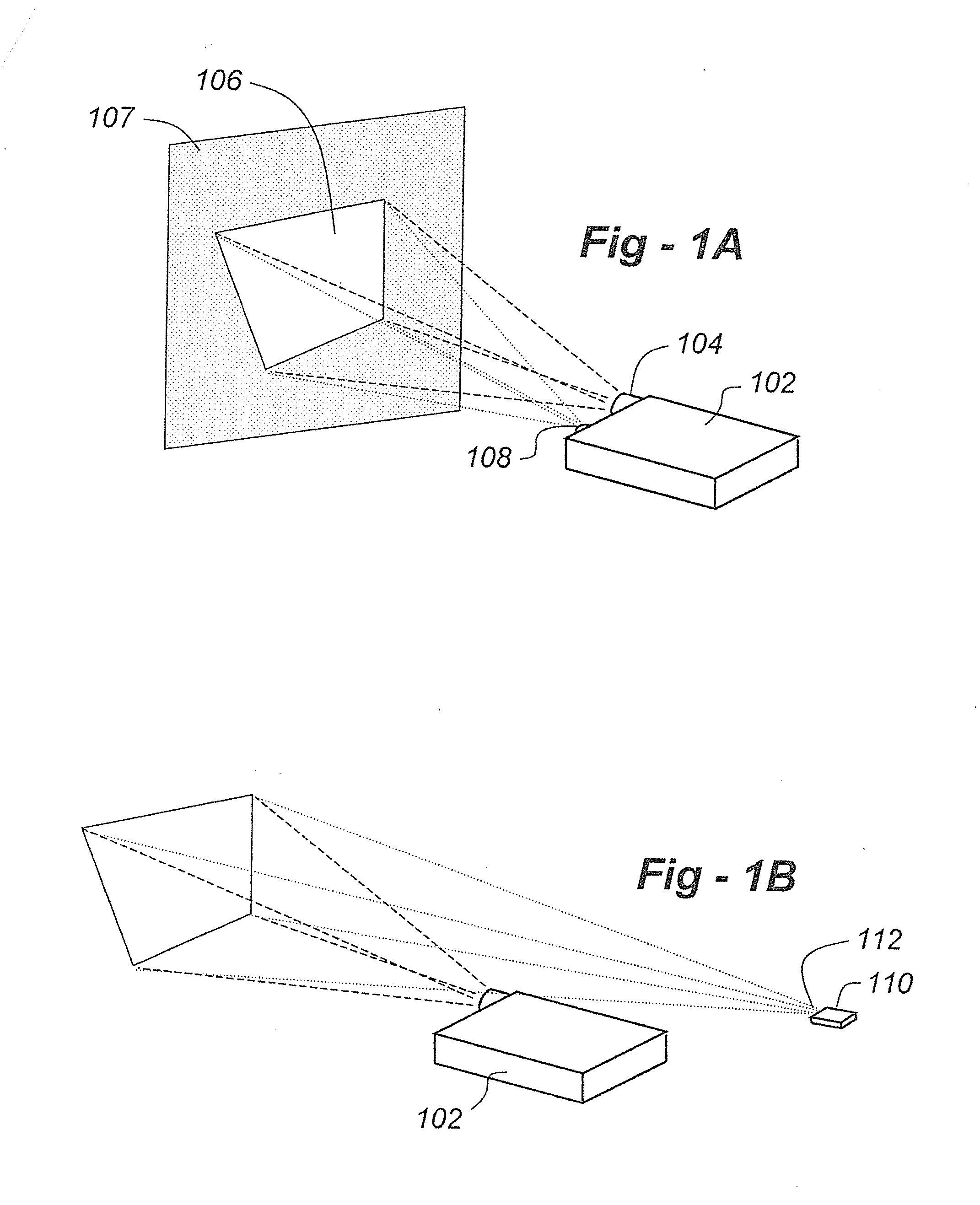
[0032]FIG. 1A illustrates one embodiment of the invention including an image projector 104 and sensor 108 integrated into a single unit 102. For the purposes of this invention, “image projector” should be taken to mean still or moving pictures (i.e., video), regardless of aspect ratio or resolution. The invention is not limited in terms of projector technology, which includes light-transmissive (i.e., LCD) and light-reflective (i.e., DLP) approaches. “Sensor” should be taken to mean any type of suitable image-gathering device, preferably a two-dimensional image sensor based upon charge-coupled devices (CCDs), for example. Although a relatively high resolution color sensor is preferred, that is not necessary to the basic implementation of the invention. To correct artifacts such as keystone effects alone, for example, a relatively low-resolution image sensor may be used, even a monochrome sensor. Also the “unit”102 should be taken to include a dedicated or stand-alone projector adapt...


PUM


Abstract

A projected still or video image is controlled with light generated by a laser pointer, for example. A device with a projector and a display controller projects an image onto a surface, and an image sensor views the projected image. A handheld device outputs a beam of light. A controller receives information from the image sensor regarding the presence or movement of light from the handheld device interacting with the projected image on the surface, and a control function is implemented if the light from the handheld device interacts with the projected image in accordance with a stored predetermined visual interactions such as encircling, “scratching,” or other movements. The controller may be programmed to recognize light of a specific laser wavelength in conjunction with a control operation.

Description

REFERENCE TO RELATED APPLICATIONS[0001]This application is a continuation-in-part of U.S. patent application Ser. No. 13 / 095,569, filed Apr. 27, 2011, which claims priority from U.S. Provisional Patent Application Ser. No. 61 / 439,208, filed Feb. 3, 2011, the entire content of both being incorporated herein by reference.FIELD OF THE INVENTION[0002]This invention relates to image and video projection systems, and, more particularly, to a system for correcting geometric and distortions introduced by projection onto imperfect surfaces.BACKGROUND OF THE INVENTION[0003]With the advent of super bright and ultra-bright light-emitting diodes and portable electronic devices that are too compact to provide displays which show a great deal of information, projected video and still images will become more popular. At the same time, since it might not be known upon which surface the light will be projected, certain undesirable image artifacts and distortions, such as keystone effects, will need t...

Claims


Application Information

Patent Timeline
Patent Type & Authority Applications(United States)
IPC IPC(8): G06F3/03G09G5/37
CPCG09G5/37G06F3/0304G06F3/0386G09G3/001G09G3/002G09G2320/06G09G2320/0693G09G2360/10H04N9/3185H04N9/3194
Inventor POSA, JOHN G.SCHWAB, BARRY H.
Owner VIDEA
Why Eureka
Try Eureka