
Underwater image projection controller with boundary setting and image correction modules and interface and method of using same

Active Publication Date: 2014-03-27
PENTAIR WATER POOL & SPA INC
View PDF4 Cites 20 Cited by
  • Summary
  • Abstract
  • Description
  • Claims
  • Application Information

AI Technical Summary

Benefits of technology

The patent text is about a projection system that can correct its images based on different types of variables, such as changes in the surface where the projection is placed, changes in fluid, and other environmental factors. The system is designed to work effectively even if there are spatial variations in the environment where the projection is placed.

Problems solved by technology

In the field of image projection, a number of obstacles are provided to accurate projection of images, especially images on a non-uniform surface.
Or similarly when the projection of the image and subsequent observation of the image are made in one fluid environment and the projected image target is in another fluid environment, resulting in unacceptable distortion.
Additionally, in projecting images in the interior of a body of water like those in water features or in targeted natural water settings, such as but certainly not limited to pools, fountains, spas, sand bars, and the like surface irregularities make correction in combination with the distortion effects difficult.
Some of the technical difficulties and issues in projecting images in these locations include accommodating the variables of transmissivity within the body of water, the variations between the transmissivity of the water and the interface with air and the location of an observer outside of the body of water, undulating contours and angles within the body of water and in the surfaces being projected upon within the body of water, observational variations based on the position of the observer, and similar variables which must be accommodated to provide ideal image viewing.

Method used


Image

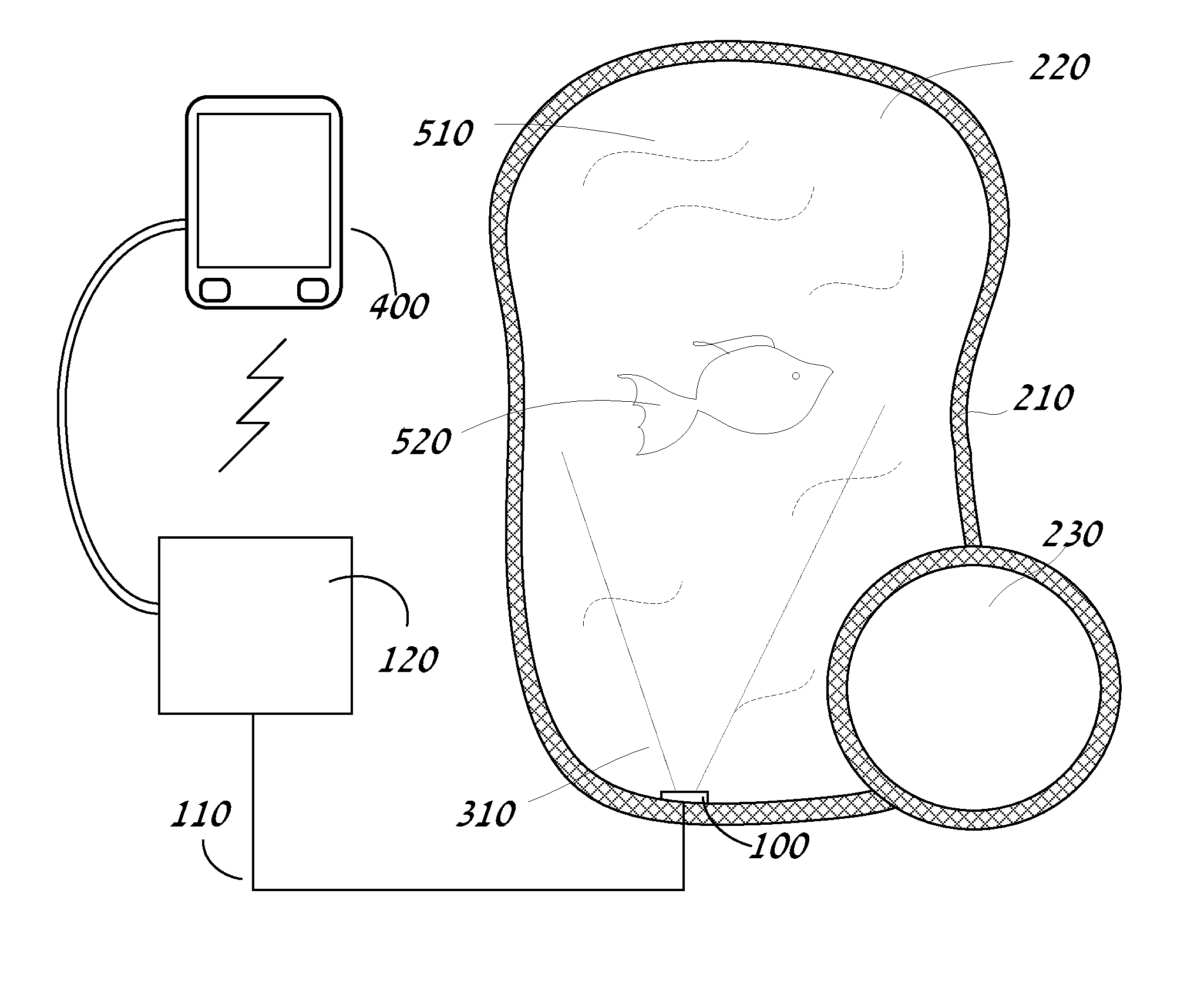
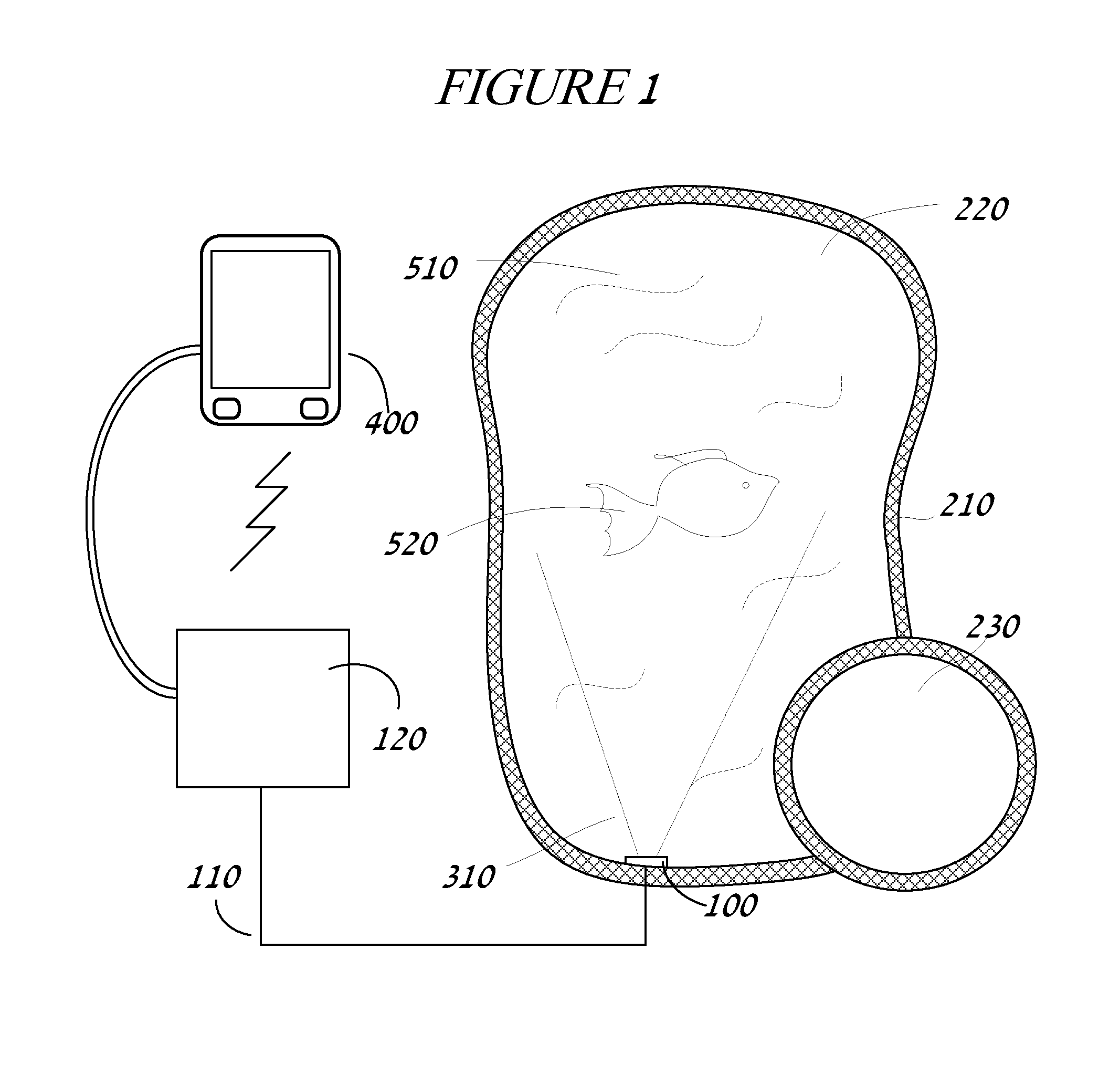
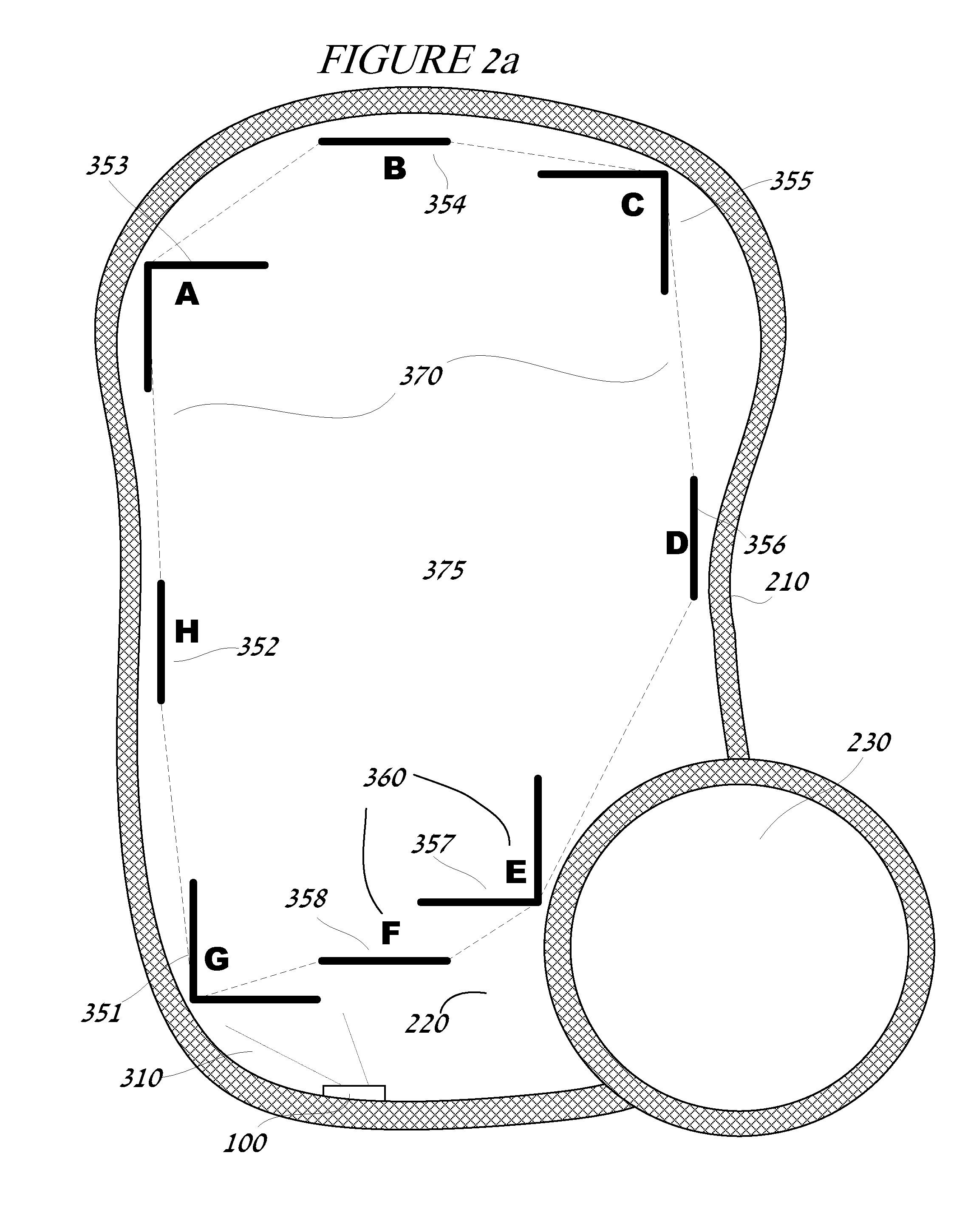
  • Underwater image projection controller with boundary setting and image correction modules and interface and method of using same
  • Underwater image projection controller with boundary setting and image correction modules and interface and method of using same
  • Underwater image projection controller with boundary setting and image correction modules and interface and method of using same

Examples


Embodiment Construction

[0037]The instant invention is directed to an underwater projection system and controller for configuring and controlling image projection in situ. Water has a different refractive index from air which adds to the optical deformation of the light as it exits a lens surface if it is out of the water, thus in-situ projection simplifies the necessary corrections. In the exemplary embodiment, both the boundary setting and the image correction modules of the controller are executed underwater so that the perspective distortion correction from projector to target is avoided. Thus, in-situ projection reduces the complexity of the corrections applied by the controller. Additionally, the boundary measurements and corrections of the exemplary embodiment of the instant invention being applied in-situ provides consistency and ease of operation. The user views the image at the target as projected in situ and applies the corrections as outlined below from outside the water. Thus, the focus of the...


PUM


Abstract

An underwater projection system, a controller and method of controlling are herein described. The controller providing, at least in part, a boundary setting module or methodology and / or an image correction module or methodology through a user interface for the underwater projection system. A user interface is provided to enable user control and input and adjustment of the image controller from an observation point outside of the media of the underwater projection system, while the adjustments are made in-situ. An optional automated edge or edge and surface detection system is also contemplated to assist in boundary detection within the water feature for the underwater image projection system.

Description

CROSS-REFERENCE TO RELATED APPLICATIONS[0001]This application claims the priority of U.S. provisional patent 61 / 678,606, filed Aug. 1, 2012, which is incorporated herein by reference.COPYRIGHT NOTICE[0002]Portions of the disclosure of this patent document contain material that is subject to copyright protection. The copyright owner has no objection to the facsimile reproduction by anyone of the patent document or the patent disclosure, as it appears in the U.S. Patent and Trademark Office patent file or records, but otherwise reserves all copyright rights whatsoever.BACKGROUND OF THE INVENTION[0003]1. Field of the Invention[0004]The invention relates to, at least in part, a computer enabled device to control a projection system, set a projection boundary, and provide image correction, a controller for controlling in part an underwater projection system, a method of controlling underwater projection systems, a method of boundary setting in an underwater projection system or controlle...

Claims


Application Information

Patent Timeline
IPC IPC(8): G03B21/53G06F3/048
CPCG03B21/56H04N9/3185H04N9/3182H04N9/3194G03B21/53G03B21/608G03B21/14H04N5/74G06F3/0488H04N9/3179
Inventor DOYLE, KEVINJOHNSON, BRUCEREDDY, RAKESH
Owner PENTAIR WATER POOL & SPA INC
Learn More