
Particle control near reticle and optics using showerhead

a technology of showerheads and shower heads, applied in the field of photolithography inspection systems, can solve the problems of inability to unacceptable problems, and prior methods that do not protect inspection systems from particles as small as 10 nm in diameter

Active Publication Date: 2014-03-27
KLA TENCOR TECH CORP +1
View PDF1 Cites 11 Cited by
  • Summary
  • Abstract
  • Description
  • Claims
  • Application Information

AI Technical Summary

Benefits of technology

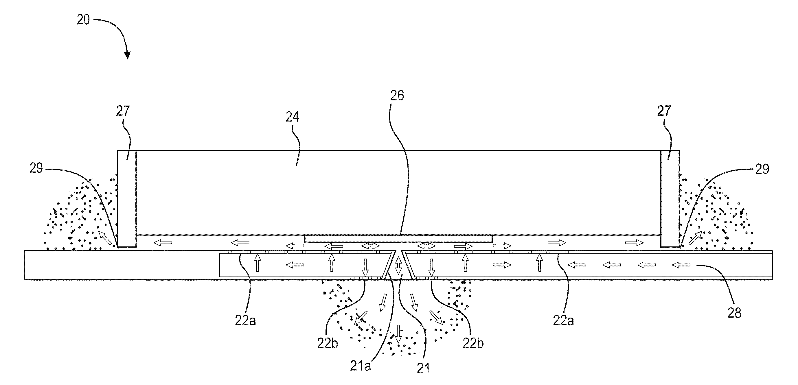
The invention is about a new kind of inspection system that uses to inspect semiconductor devices. The system is designed to keep out particles that may come from outside and contaminate the device being inspected. This is done by using a flow of pure gas that shields the reticle from particles that may come from the optics box. The technical effect of this is to create a cleaner and more reliable system for inspecting semiconductor devices.

Problems solved by technology

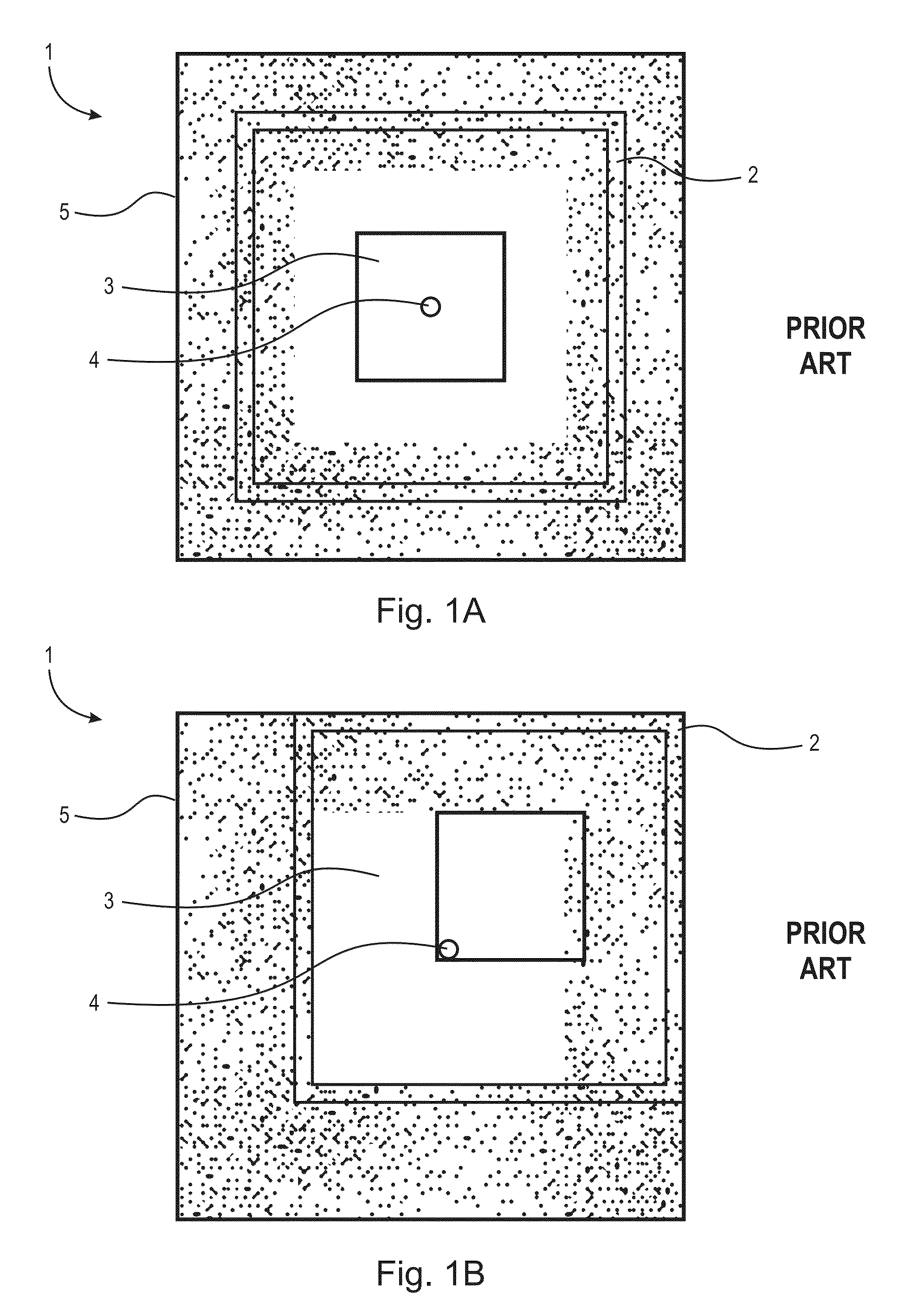
Inspection tools that use EUV light cannot use a particle protection device, such as a pellicle, that may be used with inspection tools utilizing light with longer wavelengths.
In EUV inspection systems, any particle on the reticle surface will cause unacceptable problems.
Prior methods do not protect inspection systems from particles as small as 10 nm in diameter or they have been used in processes in which reticles are cleaned after inspections.
However, with EUV inspection systems, while no cleaning is possible, particles as small as 10 nm must still be removed.
However, the thermophoresis device tends to heat the reticle thereby causing distortions in the reticle itself.

Method used


Image

  • Particle control near reticle and optics using showerhead
  • Particle control near reticle and optics using showerhead
  • Particle control near reticle and optics using showerhead

Examples


Embodiment Construction

[0022]At the outset, it should be appreciated that like drawing numbers on different drawing views identify identical structural elements of the invention. It also should be appreciated that figure proportions and angles are not always to scale in order to clearly portray the attributes of the present invention.

[0023]While the present invention is described with respect to what is presently considered to be the preferred embodiments, it is understood that the invention is not limited to the disclosed embodiments. The present invention is intended to cover various modifications and equivalent arrangements included within the spirit and scope of the appended claims.

[0024]Furthermore, it is understood that this invention is not limited to the particular methodology, materials and modifications described and as such may, of course, vary. It is also understood that the terminology used herein is for the purpose of describing particular aspects only, and is not intended to limit the scope...


PUM


Abstract

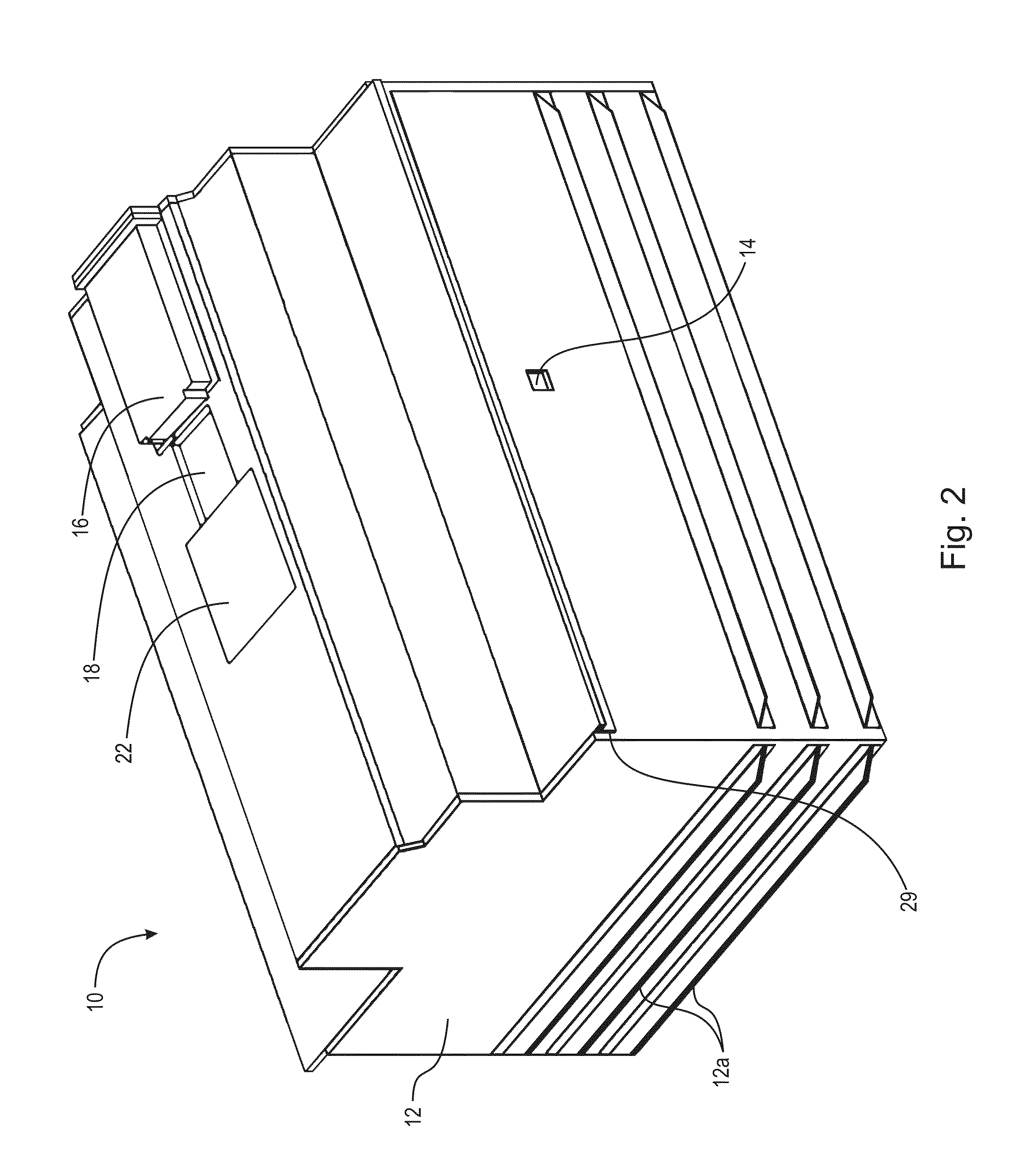
A method and an apparatus to protect a reticle against particles and chemicals in an actinic EUV reticle inspection tool are presented. The method and apparatus utilizes a pair of porous metal diffusers in the form of showerheads to provide a continual flow of clean gas. The main showerhead bathes the reticle surface to be inspected in smoothly flowing, low pressure gas, isolating it from particles coming from surrounding volumes. The secondary showerhead faces away from the reticle and toward the EUV illumination and projection optics, supplying them with purge gas while at the same time creating a buffer zone that is kept free of any particle contamination originating from those optics.

Description

CROSS-REFERENCE TO RELATED APPLICATIONS[0001]This application claims the benefit under 35 U.S.C. §119 (e) from of U.S. Provisional Application No. 61 / 706,070 filed Sep. 26, 2012 which application is incorporated herein by reference in its entirety.STATEMENT REGARDING FEDERALLY SPONSORED RESEARCH OR DEVELOPMENT[0002]The U.S. Government has a paid-up license in this invention and the right in limited circumstances to require the patent owner to license others on reasonable terms as provided for by the terms of Contract No. DE-AC04-94AL85000 awarded by the Department of Energy.FIELD OF THE INVENTION[0003]The present invention relates to the field of photolithography inspection systems, particularly to extreme ultraviolet (EUV) light inspection systems, and more particularly particle free EUV inspection systems.BACKGROUND OF THE INVENTION[0004]Inspection tools that use EUV light cannot use a particle protection device, such as a pellicle, that may be used with inspection tools utilizing...

Claims


Application Information

Patent Timeline
IPC IPC(8): G03F7/20
CPCG03F7/70841G01N21/956G01N2021/95676G03F1/84G03F7/70916G03F1/68G03F7/70933
Inventor DELGADO, GILDARDO R.CHILESE, FRANKGARCIA, RUDYTORCZYNSKI, JOHN R.GELLER, ANTHONY S.RADER, DANIEL J.KLEBANOFF, LEONARD E.GALLIS, MICHAIL A.
Owner KLA TENCOR TECH CORP
Learn More