
Thermally-Managed Electronic Device

a technology of electronic devices and cooling components, which is applied in the direction of semiconductor devices for light sources, lighting and heating apparatus, and support devices for lighting, etc., can solve the problems of insufficient thermal energy removal from high-power devices, thermal management issues, and conventional heat sinks, fans and finned elements, etc., and achieve the effect of improving heat removal capacity

Inactive Publication Date: 2014-03-27
PFG IP
View PDF15 Cites 1 Cited by
  • Summary
  • Abstract
  • Description
  • Claims
  • Application Information

AI Technical Summary

Benefits of technology

The invention is a device that manages heat for electronic devices. It uses a heat pipe and multiple heat-radiating elements to help remove heat from a heat source. The device can be used in natural or forced air convection and increases the heat-removing surface area by using multiple heat-radiating elements connected by thermal connectors. This improves the heat removal on the cold side of the heat pipe.

Problems solved by technology

Similarly, thermal management issues arise with the use of high-power transistor or resistor elements in higher-power electronic systems
Conventional heat sinks, fans and finned elements are unable to adequately remove sufficient thermal energy from these state of the art, high-power devices.

Method used


Image

  • Thermally-Managed Electronic Device
  • Thermally-Managed Electronic Device
  • Thermally-Managed Electronic Device

Examples


Embodiment Construction

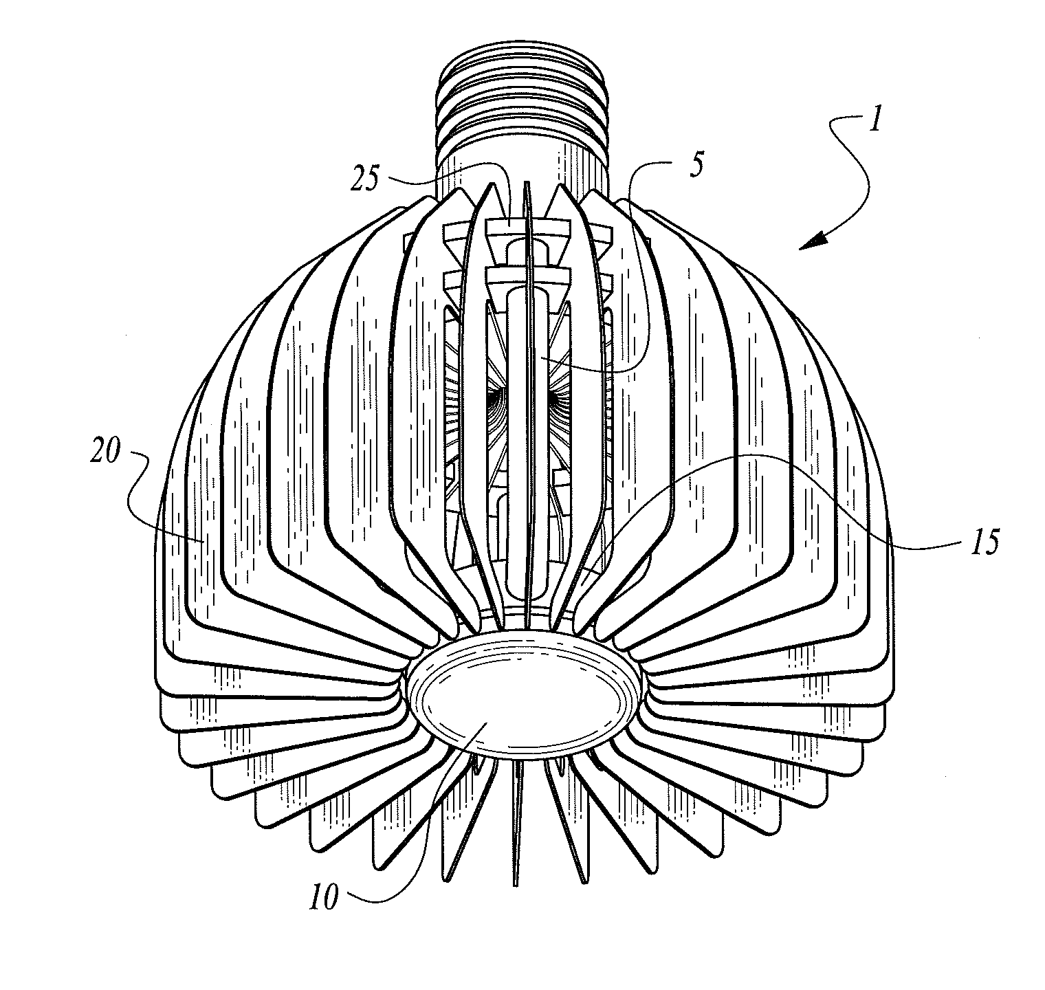
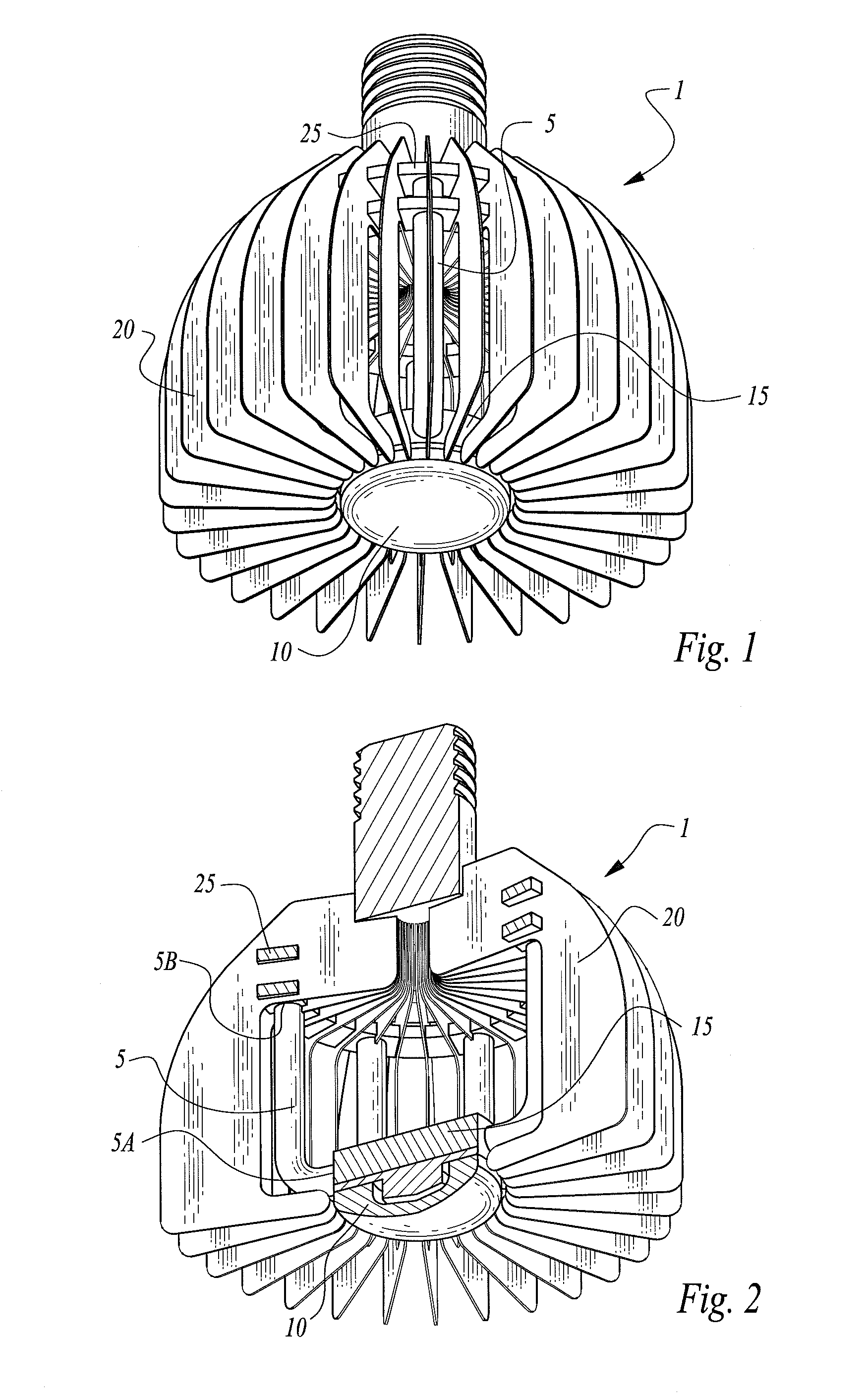
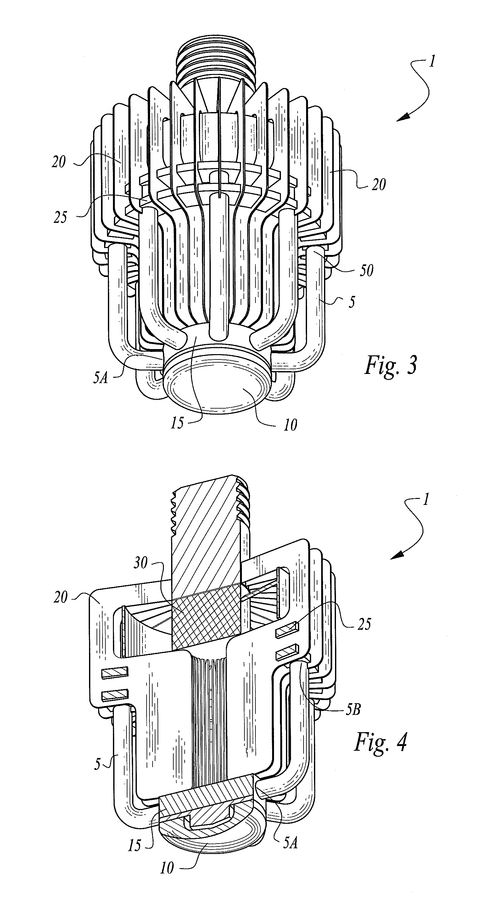
[0036]Turning now to the figures wherein like references define like elements among the several views, Applicant discloses a thermally-managed electronic device 1 such as an LED lamp assembly or microelectronic assembly with active heat removal using a heat-pipe 5 in cooperating with a heat source element 10 such as an LED lamp or microelectronic module or electronic component as is shown in FIGS. 1-4.

[0037]It is expressly noted that the heat source element 10 of the claims of the invention is not limited to an LED or incandescent lamp or microelectronic module or electronic component, but rather may comprise any element that acts as a heat source including without limitation any mechanical, electrical or chemical source of heat.

[0038]FIGS. 1 and 2 depict the device 1 of the invention having a heat source element 10 in a natural convection embodiment.

[0039]FIGS. 3 and 4 depict device 1 of the invention having a heat source element 10 in a forced-air convection embodiment.

[0040]As re...


PUM


Abstract

A thermally-managed electronic device, such as a heat-generating lamp or microelectronic assembly, takes advantage of the latent heat of phase-change within a heat pipe and functions in cooperation with a plurality of heat-radiating elements to enhance heat removal capacity from a heat source. The device, which may be provided in a natural convection or forced air convection embodiment, improves the heat removal on the cold side of the heat pipe by providing a much larger heat-radiating surface area in the form of a plurality of heat-radiating elements that are each thermally connected by means of one or more thermal connecting elements.

Description

CROSS-REFERENCE TO RELATED APPLICATIONS[0001]This application claims the benefit of U.S. Provisional Patent Application No. 61 / 539,298, filed on Sep. 26, 2011 entitled “LED Lamp Cooling Device” pursuant to 35 USC 119, which application is incorporated fully herein by reference.STATEMENT REGARDING FEDERALLY SPONSORED RESEARCH AND DEVELOPMENT[0002]N / ABACKGROUND OF THE INVENTION[0003]1. Field of the Invention[0004]The invention relates generally to the field of microelectronic and LED cooling devices and methods. More specifically, the invention relates to a thermally-managed microelectronic or LED lamp cooling assembly that uses the latent heat of phase-change inside heat pipes to significantly improve heat removal from a heat source and enhance heat removal capacity on the cold side of the heat pipe by providing increased surface area in the form of cooling fins.[0005]2. Description of the Related Art[0006]It is well-known that thermal management of heat-generating devices such as el...

Claims


Application Information

Patent Timeline
IPC IPC(8): H05K7/20F21V29/00
CPCF21V29/773F21K9/23F21Y2115/10
Inventor SAPIR, ITZHAK
Owner PFG IP
Learn More