Vehicle illumination apparatus

a technology for illumination apparatus and led headlights, which is applied in the direction of lighting and heating apparatus, fixed installation, semiconductor devices for light sources, etc., can solve the problems of reducing the utilization efficiency, reducing the efficiency of the light source of the led low beam, and reducing the efficiency of the utilization efficiency, so as to achieve a strong forward light output

Inactive Publication Date: 2014-03-27
CORETRONIC
View PDF8 Cites 21 Cited by
  • Summary
  • Abstract
  • Description
  • Claims
  • Application Information

AI Technical Summary

Benefits of technology

[0008]The invention is directed to an illumination apparatus used in vehicle, and the illumination apparatus is capable of simultaneously providing strong forward light output and wide-range illumination.
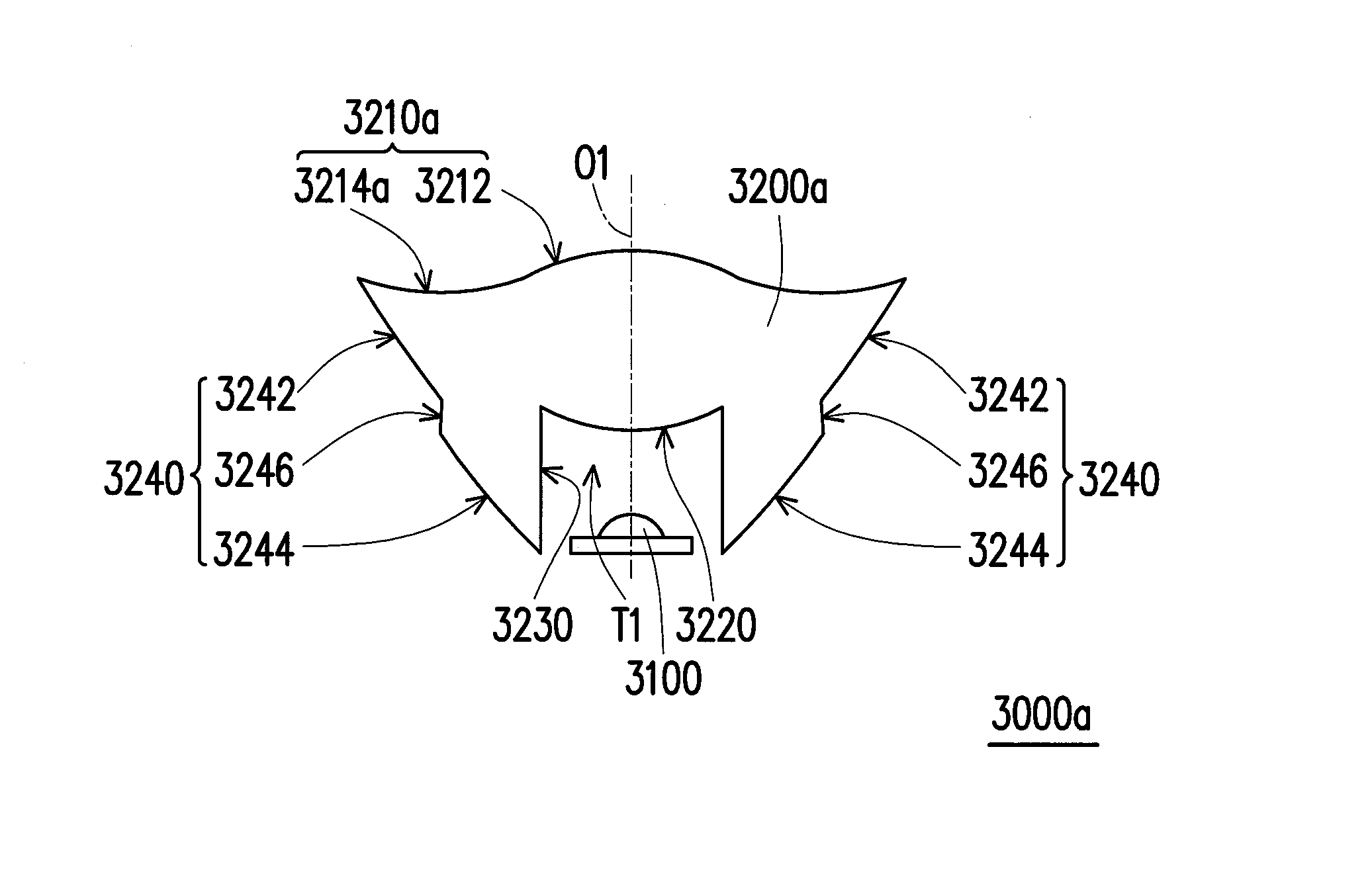
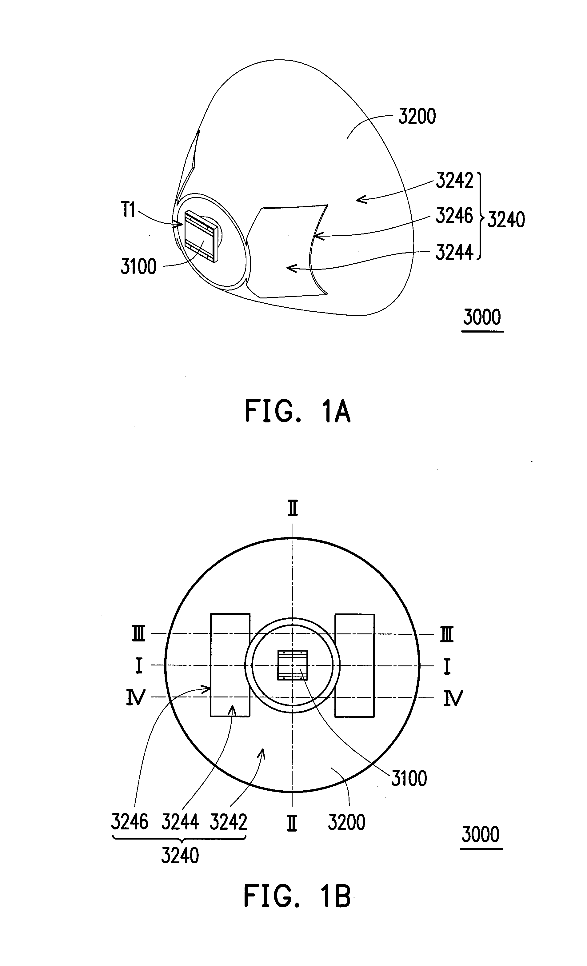
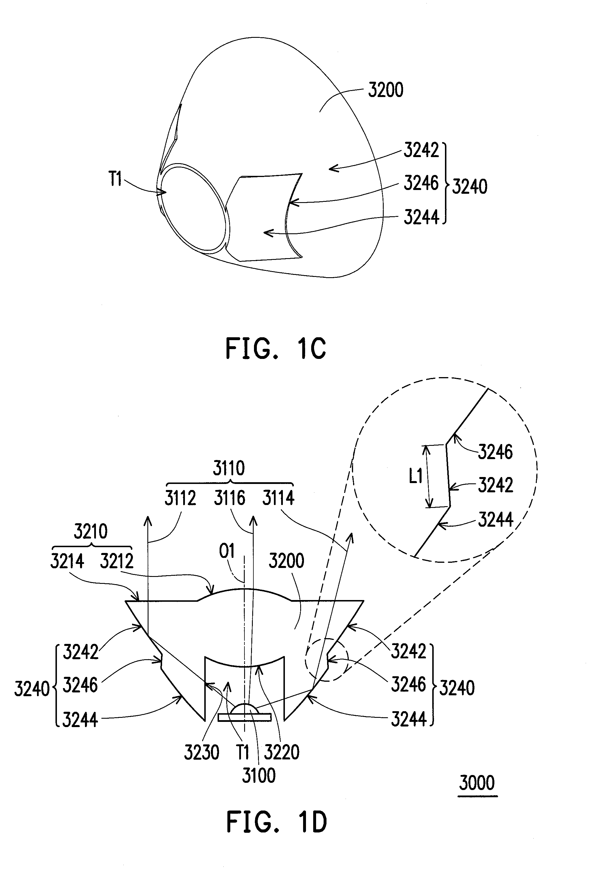
[0043]As discussed above, in the vehicle illumination apparatus described in an embodiment of the invention, the condensing and diverging lens has the light condensing region that may condense the first sub-beam, such that the resultant vehicle illumination apparatus is able to provide the strong forward light output. In addition, the condensing and diverging lens also has the light diverging region, and therefore the resultant vehicle illumination apparatus is also capable of providing the wide-range illumination. Moreover, based on total reflection and refraction principles, different regions on the outer surrounding surface of the collimating lens of the vehicle illumination apparatus described herein are designed to have different curved surfaces, and the neighboring regions have steps therebetween, so as to form divergent light patterns at different angles. Thereby, the light pattern of the illumination beam projected out of the collimating lens in the vehicle illumination apparatus has a substantially clear cut-off line, a specific converging region, and a high light utilization rate.

Problems solved by technology

At present, the cost of the LED headlight remains high due to the needs of high-wattage LEDs and large heat sinks.
However, the shielding plate also leads to reduction of utilization efficiency (e.g., at most 60% of the total efficiency) of the light source of the LED low beam.

Method used


Image

  • Vehicle illumination apparatus
  • Vehicle illumination apparatus
  • Vehicle illumination apparatus

Examples


Embodiment Construction

[0131]In the following detailed description of the embodiments, reference is made to the accompanying drawings which form a part hereof, and in which are shown by way of illustration specific embodiments in which the invention may be practiced. In this regard, directional terminology, such as “top,”“bottom,”“front,”“back,” etc., is used with reference to the orientation of the Figure(s) being described. The components of the invention can be positioned in a number of different orientations. As such, the directional terminology is used for purposes of illustration and is in no way limiting. On the other hand, the drawings are only schematic and the sizes of components may be exaggerated for clarity. It is to be understood that other embodiments may be utilized and structural changes may be made without departing from the scope of the invention. Also, it is to be understood that the phraseology and terminology used herein are for the purpose of description and should not be regarded a...


PUM


Abstract

A vehicle illumination apparatus includes at least one illumination light source and at least one light guiding lens. The illumination light source is capable of providing an illumination beam. The light guiding lens includes a first light transmissive surface, a second light transmissive surface opposite to and smaller than the first light transmissive surface, an inner surrounding surface, and an outer surrounding surface. The first light transmissive surface is capable of projecting the illumination beam out of the light guiding lens. The inner surrounding surface and the second light transmissive surface are connected to each other and define a containing space configured to accommodate the illumination light source. The outer surrounding surface is connected to the inner surrounding surface and the first light transmissive surface. Besides, the outer surrounding surface has at least one light condensing region and at least one light diverging region.

Description

CROSS-REFERENCE TO RELATED APPLICATION[0001]This application claims the priority benefits of Taiwan application serial no. 101135356, filed on Sep. 26, 2012, and Taiwan application serial no. 102115919, filed on May 3, 2013. The entirety of each of the above-mentioned patent applications is hereby incorporated by reference herein and made a part of specification.BACKGROUND OF THE INVENTION[0002]1. Field of the Invention[0003]The invention relates to an illumination apparatus. Particularly, the invention relates to a vehicle illumination apparatus.[0004]2. Description of Related Art[0005]Light-emitting diode (LED) headlights have been gradually applied in compliance with requirements for light-emitting efficiency, energy saving, and environmental protection. At present, the cost of the LED headlight remains high due to the needs of high-wattage LEDs and large heat sinks. Generally, in the existing LED low beam, a shielding plate is often required to form a clear cut-off line through ...

Claims


Application Information

Patent Timeline
Patent Type & Authority Applications(United States)
IPC IPC(8): F21S8/10F21W107/10
CPCF21S48/1225F21V5/08F21Y2115/10F21S41/143F21S41/322F21S41/336F21S41/153F21S41/24F21S41/265F21S41/285
Inventor TSAI, HAN-WENKUO, MING-FENGHUANG, KUO-SHENG
Owner CORETRONIC
Why Eureka
Try Eureka